Firewood chopping device

The technology of a wood splitter and a splitter is applied in the direction of wood splitting devices, wood processing appliances, manufacturing tools, etc., which can solve the problems of low wood splitting efficiency and low safety of wood splitting tools, and achieve the effect of high efficiency and safety.

Inactive Publication Date: 2018-07-24
CHANGZHOU COLLEGE OF INFORMATION TECH
View PDF1 Cites 1 Cited by
  • Summary
  • Abstract
  • Description
  • Claims
  • Application Information

AI Technical Summary

Problems solved by technology

[0003] The technical problem to be solved by the present invention is: in order to solve the problems of low safety and low efficiency of the existing wood splitting tools, the present invention provides a wood splitter to solve the above problems

Method used


Image

  • Firewood chopping device
  • Firewood chopping device
  • Firewood chopping device

Examples


Embodiment Construction

[0030] Embodiments of the present invention are described in detail below, examples of which are shown in the drawings, wherein the same or similar reference numerals designate the same or similar elements or elements having the same or similar functions throughout. The embodiments described below by referring to the figures are exemplary only for explaining the present invention and should not be construed as limiting the present invention.

[0031] In describing the present invention, it should be understood that the terms "center", "longitudinal", "transverse", "length", "width", "thickness", "upper", "lower", "front", " Back", "Left", "Right", "Vertical", "Horizontal", "Top", "Bottom", "Inner", "Outer", "Axial", "Radial", "Circumferential", etc. The indicated orientation or positional relationship is based on the orientation or positional relationship shown in the drawings, and is only for the convenience of describing the present invention and simplifying the description,...


PUM


Abstract

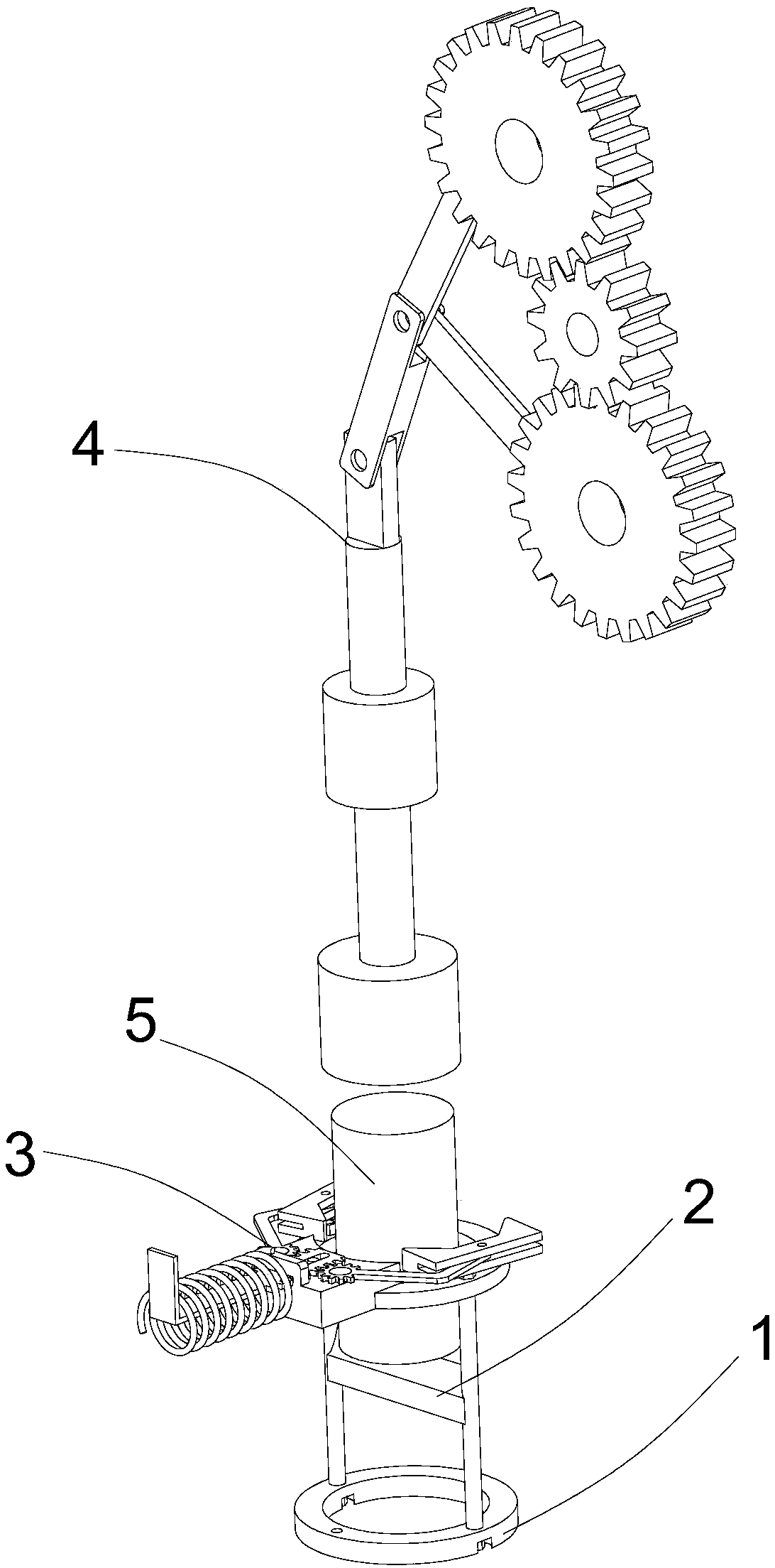
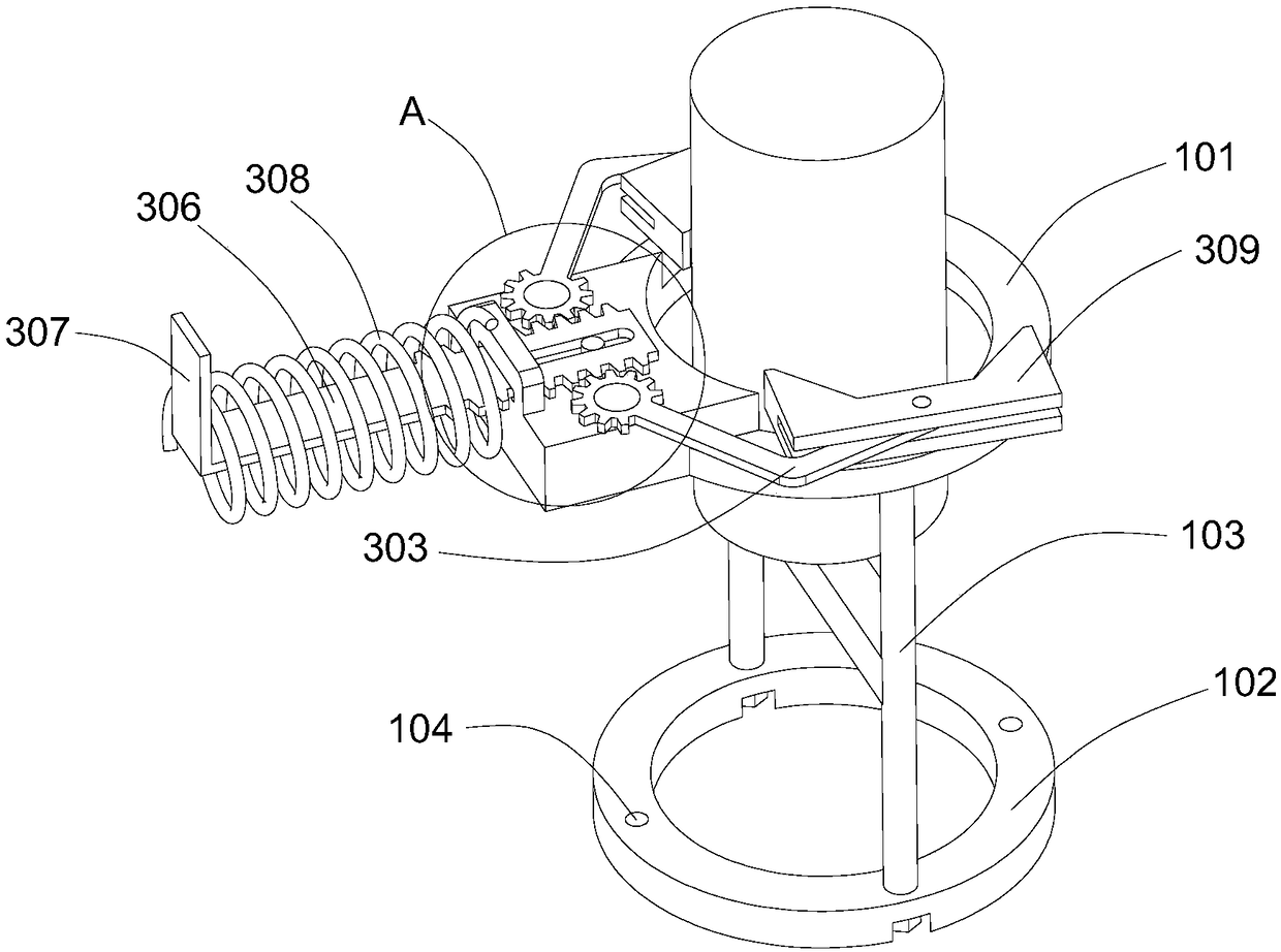
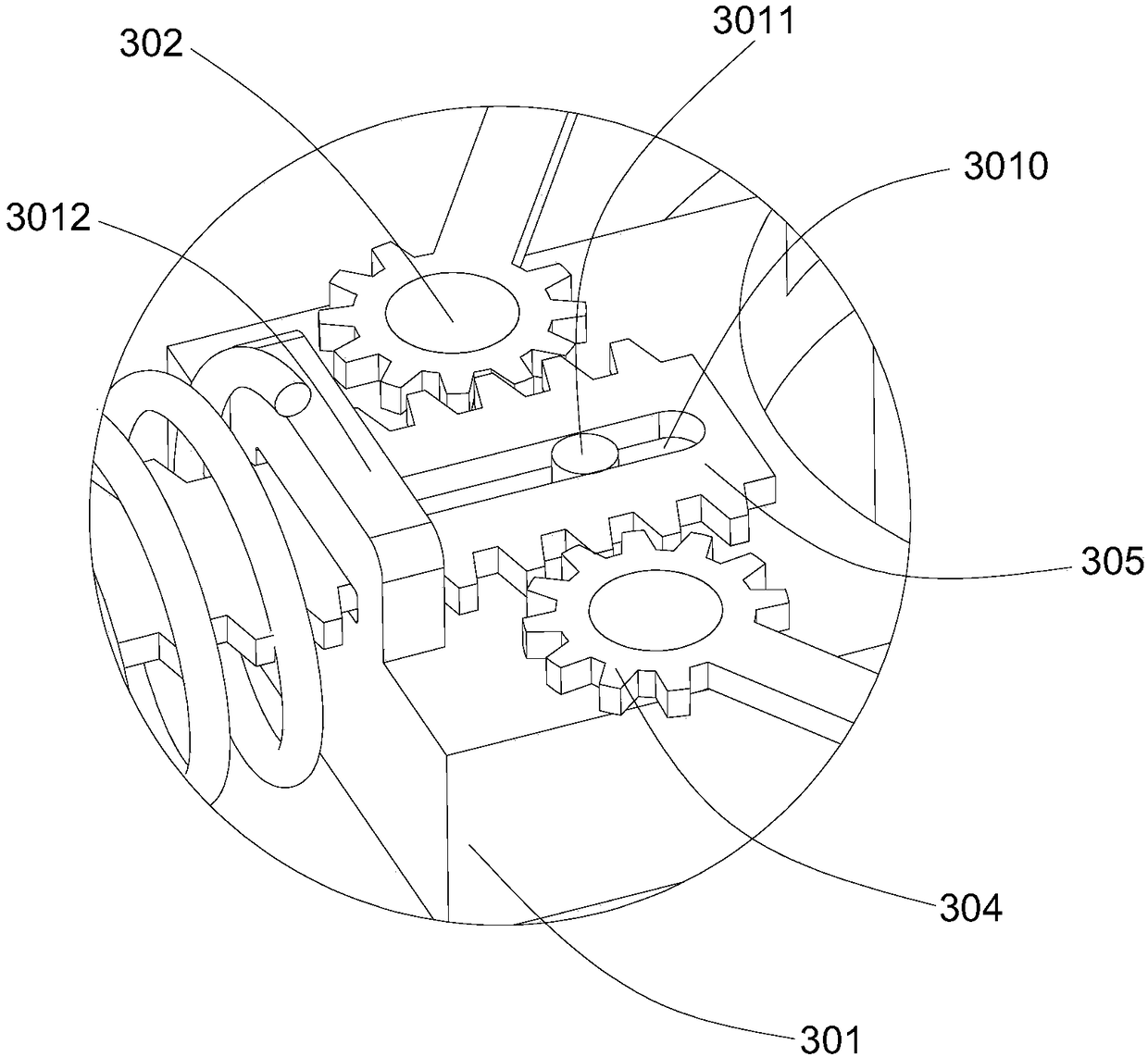
The invention provides a firewood chopping device. The firewood chopping device comprises a base, a chopper, a positioning mechanism and a knocking mechanism. The chopper is fixed to the base, a bladeof the chopper faces upwards, and a station used for storing timber is arranged on the upper portion of the chopper; the positioning mechanism is used for positioning the timber on the station; and the knocking mechanism is used for knocking the timber on the station from top to bottom. According to the firewood chopping device, the timber can be fixed reliably and knocked through the knocking mechanism, manual manufacturing is not needed, and the firewood chopping efficiency and safety are high.

Description

technical field [0001] The invention relates to a wood splitting tool, in particular to a wood splitter. Background technique [0002] In order to produce firewood, an ax can be used to split logs into several pieces. This method of chopping wood is very traditional, not only time-consuming, labor-intensive, inefficient, but also has high potential safety hazards; it can also be done with firewood tools. For example, the authorized announcement is CN206678120U The Chinese patent of discloses a kind of labor-saving and safe firewood chopping device, solves the problems of laborious and time-consuming firewood chopping in the prior art and potential safety hazards. The invention includes a base with a ring structure and horizontal upper and lower end surfaces, a first support column and a second support column fixed on the upper end surface of the base, a protective ring, and an ax with an upward edge, the first support column and the second support The columns are arranged s...

Claims


Application Information

Patent Timeline
Patent Type & Authority Applications(China)
IPC IPC(8): B27L7/06
CPCB27L7/06
Inventor 颜鹏罗彬宾罗腾腾
Owner CHANGZHOU COLLEGE OF INFORMATION TECH
Why Eureka
Try Eureka