Silt stopping and discharging technology and construction method for separating debris flow by adopting dynamic silt stopping reservoir capacity

A construction method and mud-rock flow technology, which is applied in sea area engineering, water conservancy engineering, construction, etc., can solve the problems of barrier structure erosion, limited interception effect, aggravating mud-rock flow disasters, etc., and achieve the effect of improving safety and improving operating conditions

Pending Publication Date: 2018-07-24
POWERCHINA HUADONG ENG COPORATION LTD
View PDF4 Cites 6 Cited by
  • Summary
  • Abstract
  • Description
  • Claims
  • Application Information

AI Technical Summary

Problems solved by technology

[0003] The above measures are effective for small and medium-sized debris flows, but for large-scale debris flows, generally 5-10m high retaining dams have limited interception effect, and are often full of mud-rock flows at one time, and most of these dams are built on the river bed cover. When a super-large debris flow comes, these unstabl

Method used


Image

  • Silt stopping and discharging technology and construction method for separating debris flow by adopting dynamic silt stopping reservoir capacity
  • Silt stopping and discharging technology and construction method for separating debris flow by adopting dynamic silt stopping reservoir capacity
  • Silt stopping and discharging technology and construction method for separating debris flow by adopting dynamic silt stopping reservoir capacity

Examples


Embodiment Construction

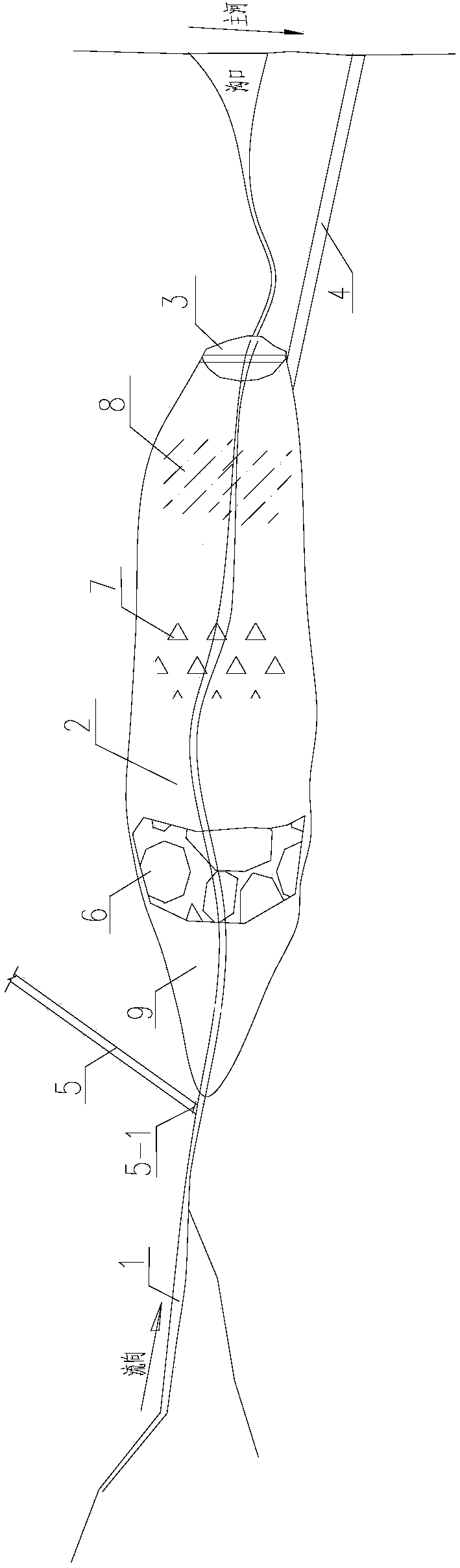
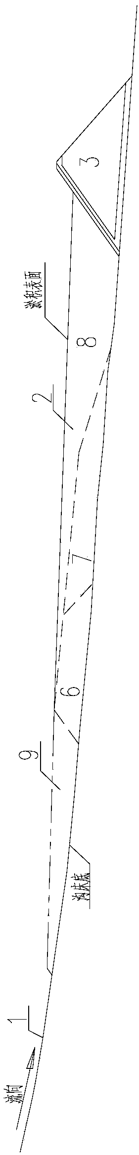
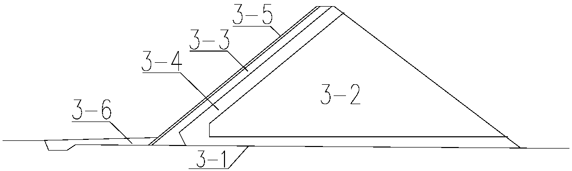
[0022] like figure 1 , figure 2 As shown, this embodiment is a drainage structure that uses dynamic silt storage capacity to separate debris flow. It has the original debris flow ditch 1, and a retaining dam 3 to block the debris flow ditch 1 is set at the gentler slope of the ditch bed of the debris flow ditch 1. , to form a debris flow silting storage capacity 2 upstream of the retaining dam 3, the debris flow silting storage capacity 2 is greater than 2 to 5 times the total amount of a debris flow, and the reservoir surface width of the debris flow silting storage capacity 2 is greater than 5 to 10 times the width of the debris flow ditch 1 . In this example, the drainage channel 4 is connected to the downstream of the debris flow storage capacity 2. The inlet elevation of drainage channel 4 is higher than the expected deposition elevation in the debris flow storage capacity 2. The flow section of drainage channel 4 is designed according to the flood discharge standard an...


PUM


Abstract

The invention relates to a silt stopping and discharging technology and a construction method for separating debris flow by adopting dynamic silt stopping reservoir capacity and aims at providing thesilt stopping and discharging technology and the construction method with convenience in construction, safety and reliability for separating debris flow by adopting the dynamic silt stopping reservoircapacity. The technical scheme adopted by the invention is that the silt stopping and discharging technology is characterized in that a water retaining dam is arranged at a proper position of a debris flow gully so as to form a debris flow silt stopping reservoir capacity on the upstream of the debris flow gully; at the initial stage of separating debris flow, debris flow solid substances are deposited in the debris flow silt stopping reservoir capacity and are separated into flood or sandy water which is safely discharged by a draining channel; after the debris flow silt stopping reservoir capacity is deposited into a gentle swale by multi-time debris flow, the flow rate of the debris flow is rapidly reduced by means of a wide reservoir surface and a gentle deposited surface gradient, sothat the debris flow loses power for coercing rock blocks; and the rock blocks are basically deposited at an inlet of a reservoir, part of small-medium particles are carried into the reservoir, and fine particles and sediment flow into, are deposited into the swale before the water retaining dam and are separated into the flood or the sandy water at an inlet of the draining channel.

Description

technical field [0001] The invention relates to a technology and a construction method for silting and discharging by using dynamic silting and storing capacity to separate mud-rock flow. It is suitable for the field of debris flow prevention and control technology in water conservancy and hydropower projects and geological disaster control projects, especially for the treatment of large debris flow ditches that cannot be solved by conventional "stabilization and drainage" measures. Background technique [0002] The geological conditions are complex and the earthquake intensity is high in the mountainous areas of western my country. Natural geological disasters such as landslides, mountain torrents, and debris flows are increasingly affecting the construction and operation of hydropower projects. The most common way to control debris flow is to build a number of retaining structures (sand dams or valley squares) along the ditch to stabilize the ditch and bed, build drainage ...

Claims


Application Information

Patent Timeline
IPC IPC(8): E02B7/02
CPCE02B7/02
Inventor 张春生徐建荣彭育何世海何明杰薛阳黄成家
Owner POWERCHINA HUADONG ENG COPORATION LTD
Why Eureka
Try Eureka