
A Method of Acceleration and Deceleration Control in Trajectory Planning of Numerical Control System

A technology of acceleration and deceleration control and numerical control system, which is applied in the field of servo system motion control, can solve the problems of numerical control system acceleration, jerk curve not smooth enough, deceleration, etc., to reduce shock and vibration, smooth jerk curve, and simple control algorithm model Effect

Active Publication Date: 2020-11-20
SUZHOU UNIV OF SCI & TECH
View PDF7 Cites 0 Cited by
  • Summary
  • Abstract
  • Description
  • Claims
  • Application Information

AI Technical Summary

Problems solved by technology

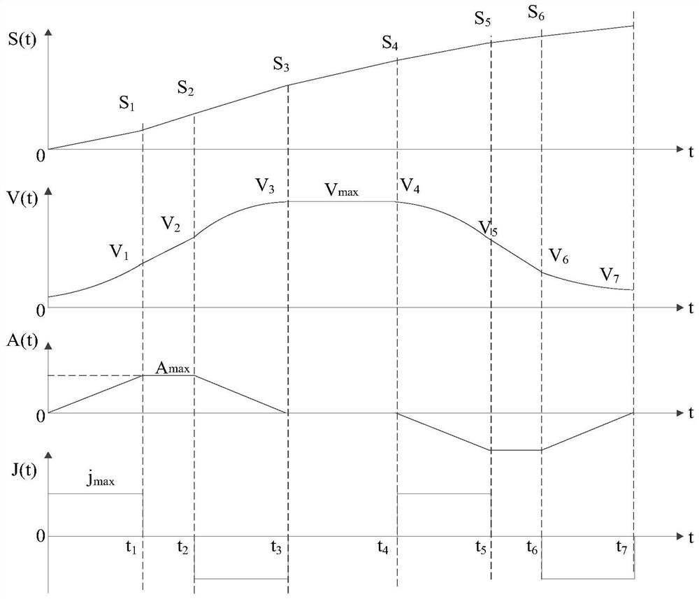
However, this acceleration and deceleration control method still has deficiencies: in the uniform acceleration section, although the jerk curves of the variable speed section and the uniform acceleration section (uniform deceleration section) are continuous, the jerk curve at the turning point is still not smooth enough, which will lead to The system is still in the state of sudden acceleration or sudden deceleration here

Method used


Image

  • A Method of Acceleration and Deceleration Control in Trajectory Planning of Numerical Control System
  • A Method of Acceleration and Deceleration Control in Trajectory Planning of Numerical Control System
  • A Method of Acceleration and Deceleration Control in Trajectory Planning of Numerical Control System

Examples


Embodiment Construction

[0024] In order to make the above-mentioned objects, features and advantages of the present invention more obvious and understandable, the specific embodiments of the present invention will be described in detail below with reference to the accompanying drawings.

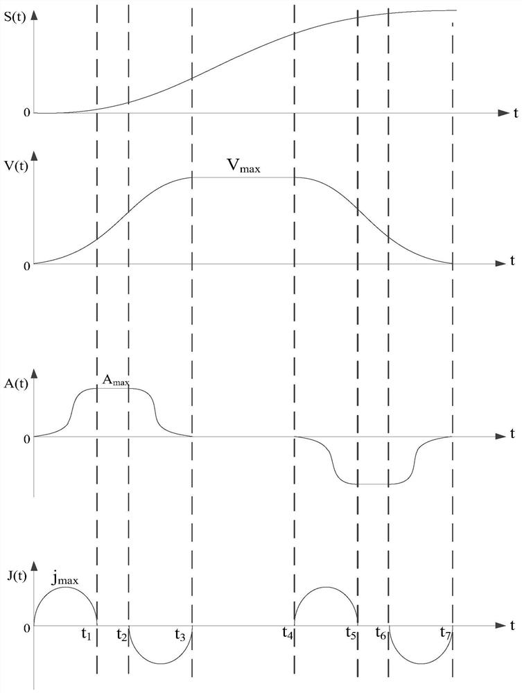
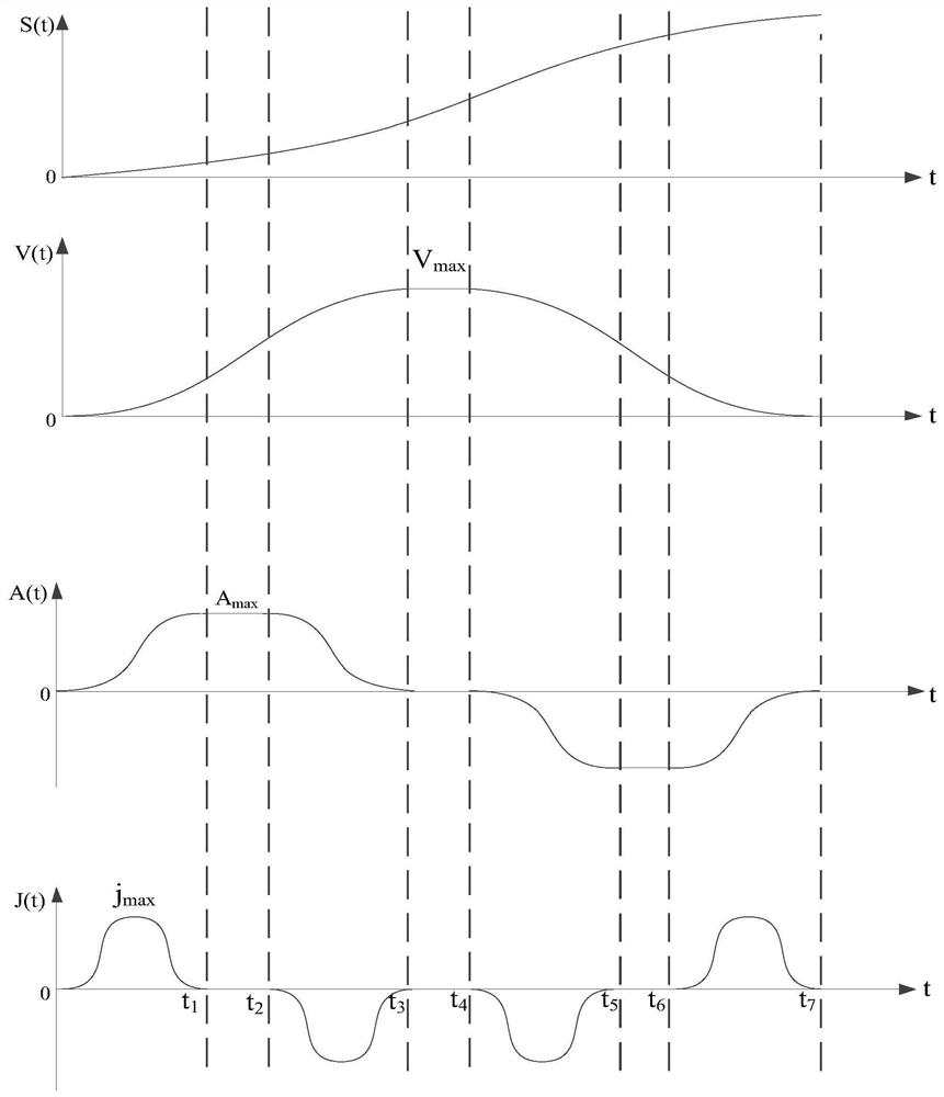
[0025] The purpose of the present invention is to provide an improved sine function square curve acceleration and deceleration control method applied to trajectory planning of a high-precision servo system. image 3 Shown is the model of the modified sine function square curve acceleration and deceleration curve, where j max Is the maximum value of jerk during operation, a max Is the maximum acceleration, V max Maximum speed allowed for processing. The whole acceleration and deceleration curve can be divided into 7 symmetrical stages, 0~t 1 Are all acceleration phases, t 1 ~t 2 Is the uniform acceleration stage, t 2 ~t 3 To reduce the acceleration phase, t 3 ~t 4 Is the uniform speed stage, t 4 ~t 5 Is the acceleratio...


PUM


Abstract

The invention provides an acceleration and deceleration control method in the trajectory planning of a numerical control system. Assuming that the total running time of the numerical control system during processing is T, the total running time is divided into seven time periods, which are respectively 0 to t 1 , t 1 ~t 2 , t 2 ~t 3 , t 3 ~t 4 , t 4 ~t 5 , t 5 ~t 6 , t 6 ~t 7 , define the time interval of each time period as T i (i=1,2,3...,7), then T 1 The corresponding time period is from 0 to t 1 , T 2 The corresponding time period is t 1 ~t 2 , T 3 The corresponding time period is t 2 ~t 3 , T 4 The corresponding time period is t 3 ~t 4 ,T 5 The corresponding time period is t 4 ~t 5 ,T 6 The corresponding time period is t 5 ~t 6 ,T 7 The corresponding time period is t 6 ~t 7 , the algorithm expression used when planning the acceleration and deceleration curve model is where j(t) is the function of jerk with respect to time t, j max For the maximum value of jerk during operation, the acceleration and deceleration control method in the trajectory planning of the numerical control system provided by the present invention intersects with the prior art, the control algorithm model is simpler, the jerk curve is smoother, and the numerical control is directly reduced. The system starts and stops.

Description

Technical field [0001] The invention relates to the field of servo system motion control, in particular to an acceleration and deceleration control method in trajectory planning of a numerical control system. Background technique [0002] Traditional linear acceleration and deceleration control is widely used because of the optimal positioning time under the conditions of given position, speed, and acceleration. However, the discontinuous acceleration at the turning point will often cause the machine to reach the end point with the desired accuracy. oscillation. Compared with linear acceleration and deceleration control, exponential acceleration and deceleration control has relatively higher smoothness and movement accuracy. But the control algorithm is more complicated, takes a long time, and there are still acceleration mutations at the start and end points of acceleration and deceleration, which will have a certain impact on the machine tool. [0003] At present, the more comm...

Claims


Application Information

Patent Timeline
Patent Type & Authority Patents(China)
IPC IPC(8): G05B19/416
CPCG05B19/4163G05B2219/36521
Inventor 朱其新费清琪刘红俐蒋全胜
Owner SUZHOU UNIV OF SCI & TECH
Learn More