
Display device and driving method thereof

A technology of a display device and a driving method, which is applied to static indicators, instruments, etc., can solve problems such as color shift and large color coordinate shift, and achieve the effect of reducing display quality

Active Publication Date: 2020-03-06
AU OPTRONICS CORP
View PDF6 Cites 0 Cited by
  • Summary
  • Abstract
  • Description
  • Claims
  • Application Information

AI Technical Summary

Problems solved by technology

[0003] However, the color coordinates of the International Commission on Illumination (CIE) color coordinates of the light-emitting diode display device between the operation mode of low grayscale (that is, low brightness) and the operation mode of high grayscale (that is, high brightness) are skewed. shift quite a lot
In this way, the light-emitting diode display device produces color changes between the operation modes of different grayscale brightness, that is, the so-called color shift problem occurs.

Method used


Image

  • Display device and driving method thereof
  • Display device and driving method thereof
  • Display device and driving method thereof

Examples


Embodiment Construction

[0044] Below in conjunction with accompanying drawing, structural principle and working principle of the present invention are specifically described:

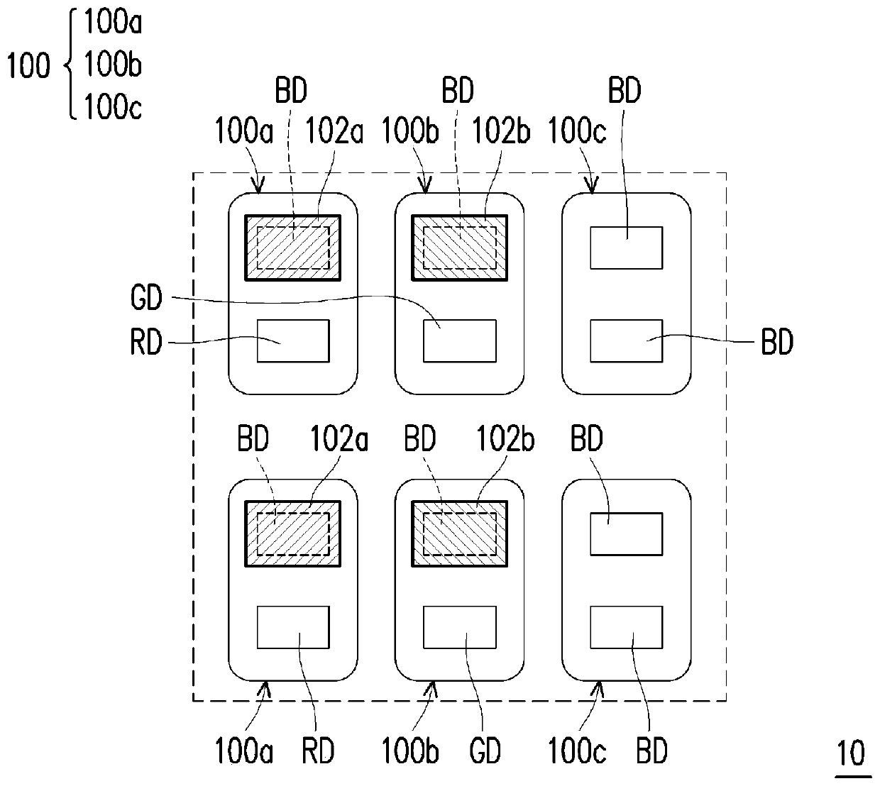
[0045] Figure 1A is a schematic top view of a pixel 100 of a display device 10 according to some embodiments of the present invention.

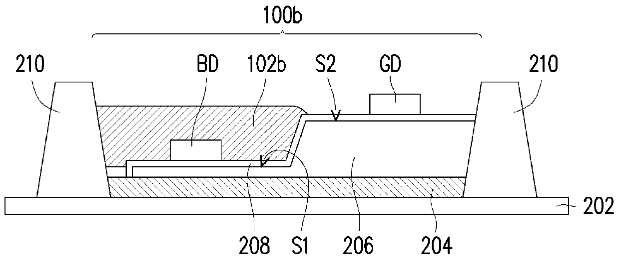
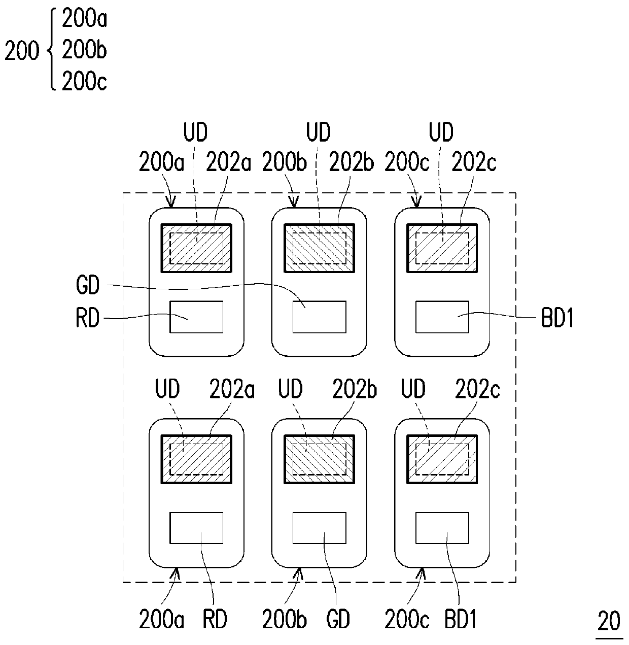
[0046] Please refer to Figure 1A , the display device 10 includes a pixel 100 . The pixel 100 includes a plurality of sub-pixels. In some embodiments, the plurality of sub-pixels includes red sub-pixels, green sub-pixels and blue sub-pixels. For example, the plurality of sub-pixels may include a sub-pixel 100a, a sub-pixel 100b, and a sub-pixel 100c. The sub-pixel 100a may be a red sub-pixel, and the dominant wavelength range of the light emitted by the sub-pixel 100a may be 610nm to 670nm. The sub-pixel 100b may be a green sub-pixel, and the dominant wavelength range of the light emitted by the sub-pixel 100b may be 510nm to 560nm. The sub-pixel 100c may be a blue sub-pixel, and the do...


PUM

PropertyMeasurementUnit
wavelengthaaaaaaaaaa

Abstract

The invention provides a display device and a driving method thereof. The display device includes a plurality of sub-pixels, at least one of which includes first and second light emitting elements inparallel with each other, and includes a wavelength conversion layer. The first illuminating element has a first starting current and the second illuminating element has a second starting current thatis greater than the first starting current. The wavelength conversion layer covers the first light emitting element and does not cover the second light emitting element. The light emitted by the wavelength conversion layer being excited by the first light emitting element has a first CIE color coordinate value (X1, Y1) in the first mode, and the light emitted by the second light emitting elementin the second mode has a second CIE color seat. The value (X2, Y2). The difference between X1 and X2 is less than 0.05, and the difference between Y1 and Y2 is less than 0.1. The gray scale range of at least one pixel in the first mode and the second mode is 1 to 127 and 128 to 255, respectively.

Description

technical field [0001] The present invention relates to a display device and its driving method, and in particular to a light emitting diode display device and its driving method. Background technique [0002] Since the light emitting diode (LED) display device has the advantages of active light emission, high brightness, high contrast, low power consumption, etc., in order to meet the requirements of high resolution, the active element array substrate and the micron light emitting diodes arranged in the array Light-emitting diode display devices composed of diodes (micro-LEDs) are one of the current development directions. [0003] However, the color coordinates of the International Commission on Illumination (CIE) color coordinates of the light-emitting diode display device between the operation mode of low grayscale (that is, low brightness) and the operation mode of high grayscale (that is, high brightness) are biased. The shift is quite large. As a result, the light-e...

Claims


Application Information

Patent Timeline
Patent Type & Authority Patents(China)
IPC IPC(8): G09G3/3225
CPCG09G3/3225
Inventor 陈振彰蔡正晔张正杰
Owner AU OPTRONICS CORP
Learn More