a coupler

A technology of couplers and moving contacts, which is applied in the field of couplers, can solve the problems of easy aging of electrical appliances, increase production costs, and shorten lifespan, and achieve the effects of solving inaccurate specified stability values, reducing production costs, and facilitating installation and assembly

Active Publication Date: 2019-11-22
佛山市汇龙温控器有限公司
View PDF5 Cites 0 Cited by
  • Summary
  • Abstract
  • Description
  • Claims
  • Application Information

AI Technical Summary

Problems solved by technology

[0002] Nowadays, the existing adjustable temperature control structure with temperature control, its function is to keep the heated product at the required set temperature to achieve the heat preservation function. The existing heat preservation structure is generally electronically controlled, that is, through a complex circuit Set the temperature control and adjustment of the heating body, because only through electronic control can the electric heating device be able to accurately determine the temperature, and the other is through an external adjustable thermostat. The structure of the thermostat is as in the Chinese patent number ZL201120090066.6, through a separate temperature control structure, assembled on the upper coupler of the electric heater, the specific structure is such as Chinese patent number ZL201310041541.4, assembled with the upper coupler to achieve the temperature adjustment effect, the defect is that the manufacturing cost High, complex installation structure, the temperature control structure of this structure adopts stepless adjustment, it is impossible to set the temperature of the electric heater very accurately, and the gear of the existing temperature control structure is separated from the separate parts of the thermostat, thereby increasing production cost
[0003] In addition, the coupler is mostly used on electric heating appliances. When the temperature sensed is equal to or exceeds the preset temperature, the first bimetal is deformed by heat and pushes the anti-dry switch action to disconnect the conductive circuit and realize anti-dry However, the first bimetal in the traditional coupler has an automatic reset function. When the temperature of the first bimetal is lower than the preset value of the reset temperature, the deformation of the first bimetal automatically resets, such as: reset temperature The default value is 50°C. The first bimetal strip disconnects the conductive line due to dry burning (overheating). If the user does not deal with the dry burning problem in time, the temperature of the first bimetal strip will be lower than 50°C after a period of heat dissipation and cooling. ℃, the first bimetal strip is reset, the conductive line is connected again, and the first bimetal strip will disconnect the conductive line due to dry burning, so repeated dry burning power off, cooling reset power on, the coupler together with the electrical appliance using the coupler It is easy to age, so that the life span is reduced, and it is easy to cause safety accidents

Method used


Image

  • a coupler
  • a coupler
  • a coupler

Examples


Embodiment 1

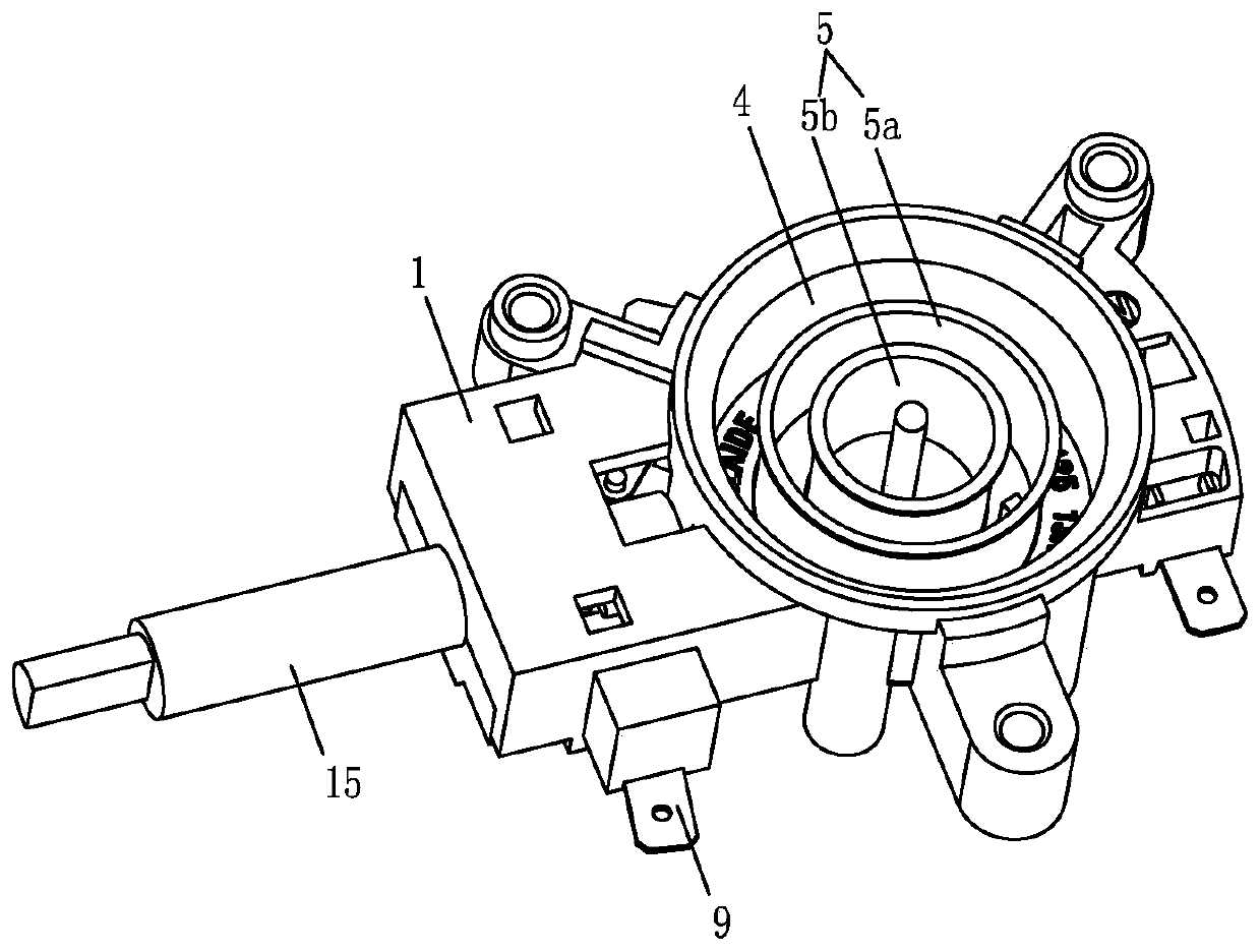
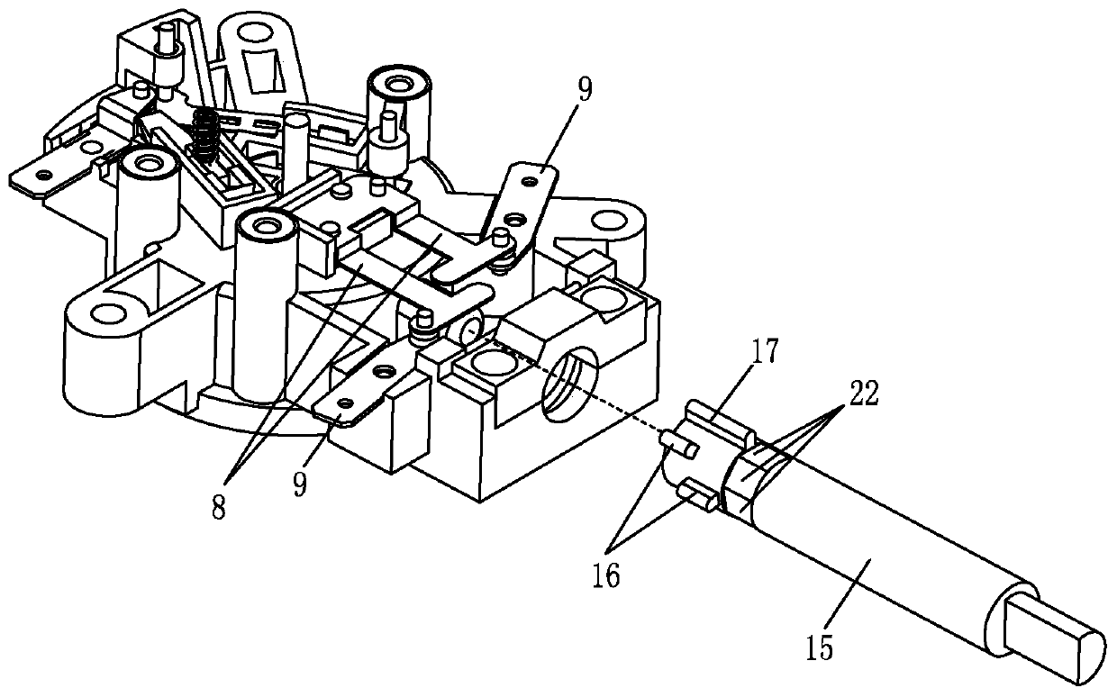
[0047] Example one, such as Figure 1 to Figure 2 As shown, a coupler includes an upper coupler 1, a plug cavity 4 is opened at the bottom of the upper coupler 1, a conductor 5 is fixed in the plug cavity 4, and a first connector connected to the conductor 5 is installed on the upper coupler 1. The movable contact piece 8, each first movable contact piece 8 is electrically connected with the corresponding first static contact piece 9, and further includes an adjusting rod 15 extending on the adjusting rod 15 to contact and cooperate with the first moving contact piece 8. Section 16. The coupler of this structure is simple and compact, quick to assemble, and reduces production costs. It enables the coupler to quickly switch on multiple heat preservation functions, and can accurately switch to the specified heat preservation value, which solves the problem of infinitely variable temperature regulation. Accurate and so on.

[0048] There are two first movable contact pieces 8 and tw...

Embodiment 2

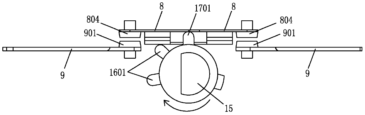
[0049] Example two, such as Figure 3 to Figure 6 As shown, the adjusting portion 16 is an adjusting convex portion 1601. By driving the adjusting rod 15, the adjusting convex portion 1601 is selectively pressed against the corresponding first movable contact piece 8, so that the first movable contact piece 8 matches the corresponding first movable contact piece 8 A static contact piece 9 is separated.

[0050] The on-off portion 17 is the on-off convex portion 1701, and the on-off convex portion 1601 is pressed against all the first moving contact pieces 8 by driving the adjusting rod 15 so that all the first moving contact pieces 8 and the first static contact piece 9 Separate and power off.

[0051] When there are two first static contact pieces 9 (for example: one first static contact piece 9 is connected to heat 100°, and the other first static contact piece 9 is connected to heat preservation 50°), the corresponding first moving contact piece 8 It is also set to two, the two...

Embodiment 3

[0053] Example three, such as Figure 7 to Figure 10 As shown, the adjusting portion 16 is an adjusting concave portion 1602. By driving the adjusting rod 15, the selected first movable contact piece 8 is pressed into the corresponding adjusting concave portion 1602, so that the first movable contact piece 8 is aligned with the corresponding first movable contact piece 8 The static contact piece 9 is turned on.

[0054] The on-off portion 17 is an on-off recess 1702. By driving the adjusting rod 15 to press all the first movable contact pieces 8 into the on-off recess 1702, all the first movable contact pieces 8 and the first static contact pieces 9 are connected and energized. .

[0055] In addition, by driving the adjusting rod 15 to press all the first moving contact pieces 8 against the outer side wall of the adjusting rod 15, all the first moving contact pieces 8 and the first static contact pieces 9 are separated and powered off.

[0056] Such as Figure 11 to Figure 18 As sh...


PUM


Abstract

A novel coupler includes an upper coupler. A plug cavity is disposed on the bottom of the upper coupler. A conductor is fixed in the plug cavity. The upper coupler is equipped with first movable contact pieces connected to the conductor. Each first movable contact piece is electrically connected to a corresponding first fixed contact piece. The novel coupler further includes an adjusting rod and an on-off portion. An adjusting portion extends from the adjusting rod and is in contact with the first movable contact pieces. By driving the adjusting rod, the adjusting portion is pressed against the corresponding first movable contact pieces one by one to separate the first movable contact piece from the corresponding first fixed contact piece, or by driving the adjusting rod, the on-off portion is pressed against all the first movable contact pieces simultaneously to separate the first movable contact piece from the first fixed contact piece. The coupler of such structure is simple and compact, quick to assemble, reduced in production cost, can be quickly switched between various heat preservation functions, and can be accurately switched to a designated terminal insulation value, andsolves inaccurate specified terminal insulation value due to stepless temperature adjustment.

Description

Technical field [0001] The invention relates to the field of couplers, in particular to a coupler. Background technique [0002] Nowadays, the existing adjustable temperature control structure with temperature control, its function is to keep the heated temperature at the required setting temperature to achieve the heat preservation function. The existing heat preservation structure generally has electronic control, that is, through a complicated circuit Setting to adjust the temperature of the heating body, because the electric heating device can only be accurately controlled by electronic control, and the other is through an external adjustable temperature controller, the structure of the temperature controller is like Chinese patent number ZL201120090066.6, through a separate temperature control structure, is assembled on the upper coupler of the electric heater. The specific structure is like the Chinese patent number ZL201310041541.4, which is assembled with the upper couple...

Claims


Application Information

Patent Timeline
Patent Type & Authority Patents(China)
IPC IPC(8): H01H37/54H01H37/04
CPCH01H37/04H01H37/54
Inventor 黄普添
Owner 佛山市汇龙温控器有限公司
Why Eureka
Try Eureka