Antenna structure and electronic equipment

An antenna structure and radiation slot technology, applied in resonant antennas, radiating element structures, components of resonant antennas, etc., can solve problems such as loss of competitiveness, achieve performance design, ensure integrity, and reduce the number of fractures Effect

Pending Publication Date: 2018-07-24
XIAMEN MEITU MOBILE TECH CO LTD
View PDF11 Cites 1 Cited by
  • Summary
  • Abstract
  • Description
  • Claims
  • Application Information

AI Technical Summary

Problems solved by technology

The usual practice is to restrict some industrial design (Industrial Design, ID) constraints to compensate for the antenna environment, for example: the design of the metal frame has to be abandoned, and the design of the metal back cover has to be abandoned. There are many seams on the appearance of the frame, and metal strips are cut out to design the antenna, which often loses the competitiveness of the ID

Method used


Image

  • Antenna structure and electronic equipment
  • Antenna structure and electronic equipment
  • Antenna structure and electronic equipment

Examples


Embodiment

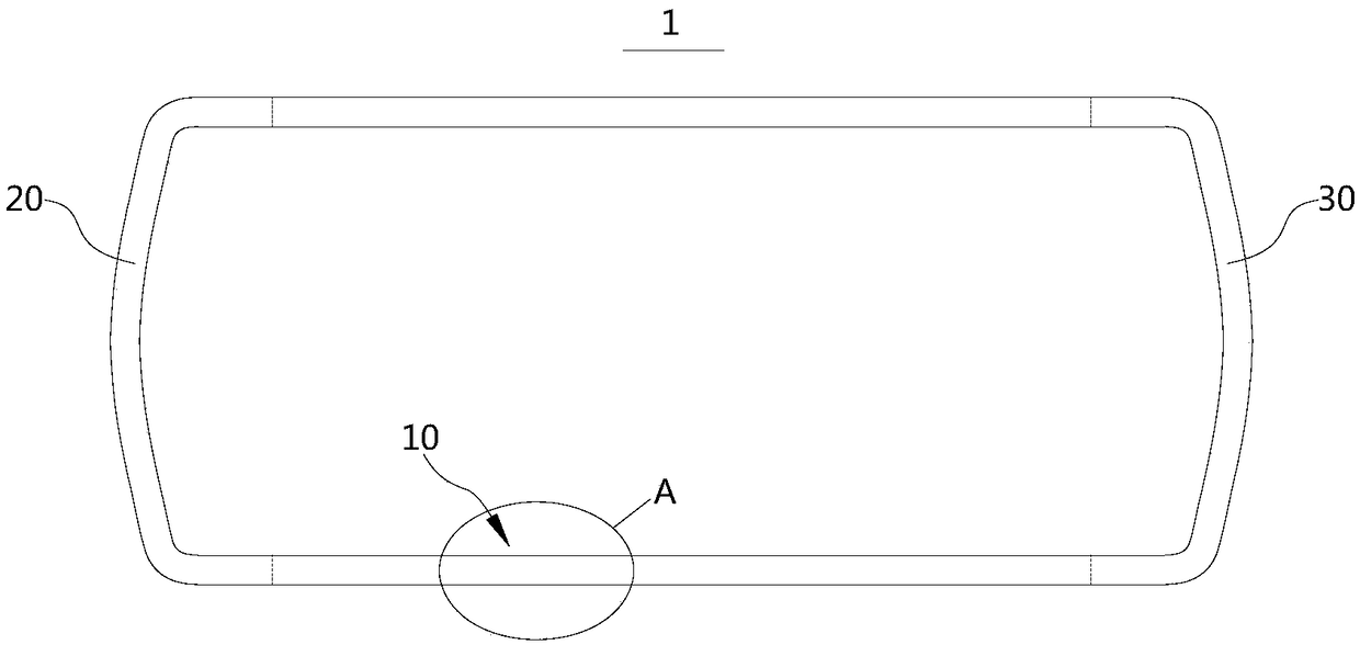
[0030] see figure 1 , this embodiment provides an antenna structure 10, which can be applied to an electronic device 1, figure 1 A indicates the specific position where the antenna structure 10 is disposed on the electronic device 1 in this embodiment. The electronic device 1 can be a mobile phone, a tablet computer, a palmtop computer and the like. The electronic device 1 may include a metal upper frame 20 , a metal lower frame 30 and the aforementioned antenna structure 10 , and the antenna structure 10 is connected to the metal upper frame 20 and the metal lower frame 30 respectively. The electronic device 1 adopts the antenna structure 10 to meet the requirements of adding antennas, realize antenna performance design, reduce the number of broken seams, realize antenna performance on the basis of continuous seams on the appearance surface, and ensure the integrity of the metal ID.

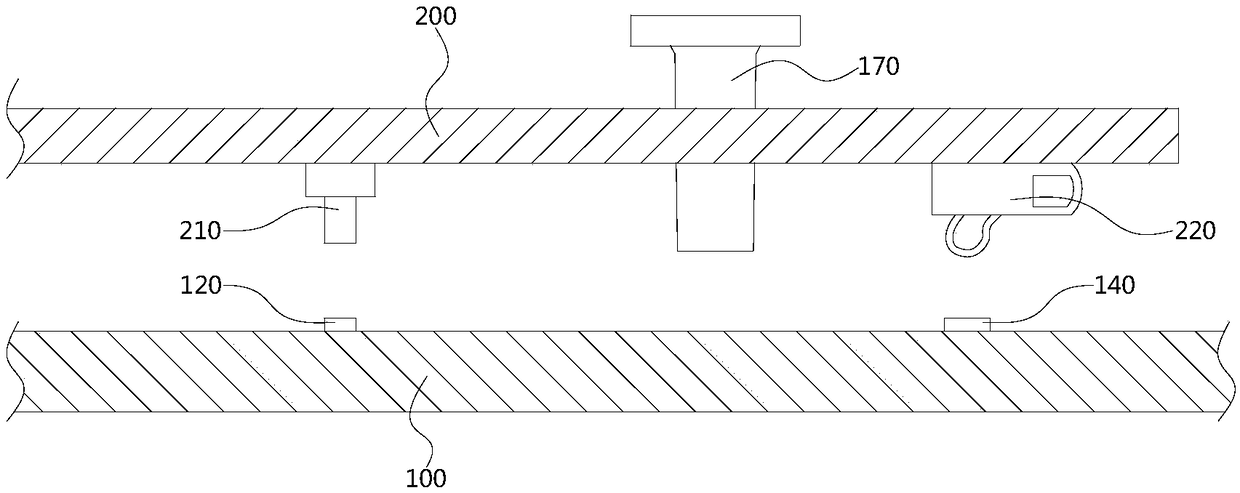
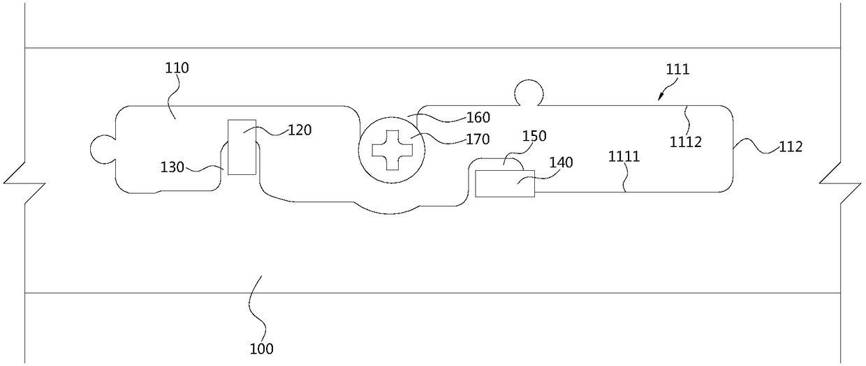
[0031] Please refer to figure 2 and image 3 , the antenna structure 10 includes a meta...


PUM


Abstract

The embodiment of the invention provides an antenna structure and electronic equipment, and relates to the field of electronic equipment. The antenna structure comprises a metallic middle frame and amain board, wherein a radiation groove is formed in the metallic middle frame; a first connecting part is arranged on the edge of the radiation groove; the projection of the first connecting part on the surface of the metallic middle frame is completely or partially positioned within the radiation groove; a feed point connecting part is arranged on the main board; the feed point connecting part isconnected with a first connecting part. According to the antenna structure and the electronic equipment provided by the embodiment of the invention, the radiation groove is formed in the metallic middle frame, the radiation groove is adopted as an antenna, then a metallic environment which has influence on an antenna is utilized and designed as the antenna, the requirement that an antenna needs to be added can be met, the antenna performance design can be achieved, in addition, the number of broken gaps can be reduced, and the completeness of metallic ID (identification) can be ensured.

Description

technical field [0001] The present invention relates to the field of electronic equipment, in particular, to an antenna structure and electronic equipment. Background technique [0002] At present, with the increase and enhancement of mobile phone functional modules (multi-camera, multi-front fill light, stereo receiver, multi-MIC noise reduction, etc.) and the trend of full-screen design, the antenna space is further squeezed. The number has not decreased but has increased, such as WIFI 2*2MIMO and LTE 4*4MIMO. Simply put, the space has become smaller and the number of antennas has increased. The usual practice is to restrict some industrial design (Industrial Design, ID) constraints to compensate for the antenna environment, for example: the design of the metal frame has to be abandoned, and the design of the metal back cover has to be abandoned. There are many seams on the appearance of the frame, and metal strips are cut to design the antenna, which often loses the comp...

Claims


Application Information

Patent Timeline
Patent Type & Authority Applications(China)
IPC IPC(8): H01Q1/38H01Q9/06
CPCH01Q1/38H01Q9/06
Inventor 张黄德马金山宋军华
Owner XIAMEN MEITU MOBILE TECH CO LTD
Why Eureka
Try Eureka