

Gas phase diffusion/ reaction laser metal 3D printing system and method
A 3D printing and laser technology, applied in the field of additive manufacturing, can solve problems such as limitations, prolonging product forming time, and reducing production efficiency, and achieve the effects of avoiding pollution, easier control of gas input, and improving work efficiency
- Summary
- Abstract
- Description
- Claims
- Application Information
AI Technical Summary
Problems solved by technology
Method used
Image

Examples
Embodiment Construction
[0024] In order to make the object, technical solution and advantages of the present invention clearer, the present invention will be further described in detail below in conjunction with the accompanying drawings and embodiments. It should be understood that the specific embodiments described here are only used to explain the present invention, not to limit the present invention. In addition, the technical features involved in the various embodiments of the present invention described below can be combined with each other as long as they do not constitute a conflict with each other.
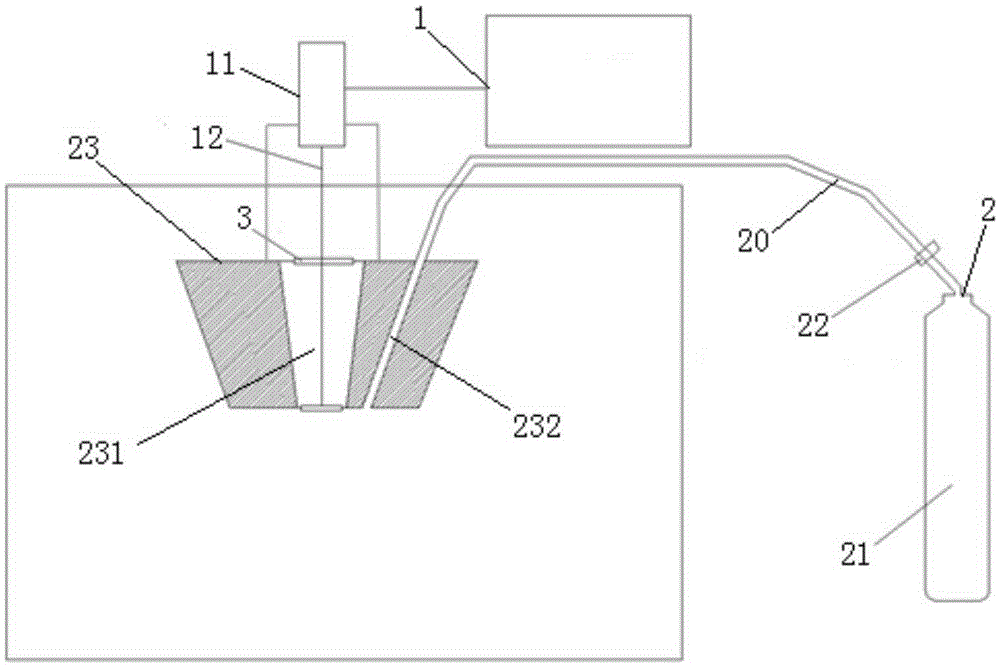
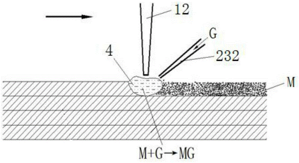
[0025] refer to figure 1 , figure 2 , a gas phase diffusion / reaction laser metal 3D printing system, including a selective laser melting forming device 1, and a ventilation device 2, wherein,
[0026] The ventilation device 2 includes an air storage tank 21, a gas pipe 20 and a nozzle 23, the gas pipe 20 is installed on the gas storage tank 21, and the nozzle 23 is fixedly installed on the la...
PUM
 Abstract
Description
Claims
Application Information