Transfer bed

A technology of transfer bed and flexible belt, which is applied in the field of transfer bed, can solve the problems of large range of body movement of patients, throwing out of patients, and potential safety hazards, so as to reduce the risk of secondary injuries, eliminate the tightness of cloth belts, and ensure The effect of stability and reliability

Inactive Publication Date: 2018-07-27
浙江佑仁智能机器人有限公司 +1
View PDF5 Cites 1 Cited by
  • Summary
  • Abstract
  • Description
  • Claims
  • Application Information

AI Technical Summary

Problems solved by technology

However, there are the following problems in this transfer robot of the prior art: 1) the driving part of the transfer mechanism and the driving part of the traveling mechanism are all integrated together, so the size of the robot along the thickness direction is bound to be large, and when This thicker robot gradually penetrates into the gap between the patient's back and the bed surface, so that when the patient is raised, it will inevitably lead to a larger range of motion of the patient's body, which obviously cannot reduce the patient's transfer process. The purpose of reducing the risk of secondary injury by moderate body movement range
2) The above-mentioned existing robot is a two-way robot. Although it can choose to lift the patient from any side of the patient, thereby improving the flexibility of the equipment, it is prone to the risk of the patient slipping from one side. Secondly, when the robot There are certain failures during use (such as failure of the position sensor, failure of the motor braking system, etc.), which can easily cause the patient to be lifted from one side and thrown out from the other side during over-travel movement, so there is a certain degree of safety Hidden danger

Method used


Image

  • Transfer bed
  • Transfer bed
  • Transfer bed

Examples


Embodiment 1

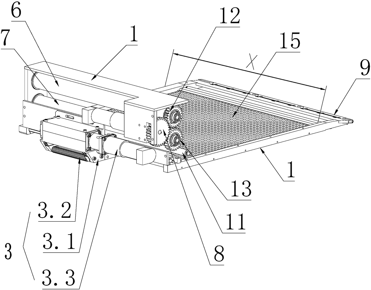
[0065] The present invention provides a kind of transfer bed, it comprises such as figure 1 or Figure 7 Shown frame 1 and flexible belt 2, flexible belt 2 is arranged on the frame 1, and the bottom of frame 1 is provided with running gear 3, is used to drive frame 1 to move, and the top of described running gear is provided with for bearing The working area of ​​the patient, the part of the flexible belt located in the working area is tightened to form a supporting surface for lifting the patient, and it is characterized in that it also includes an equipment installation area outside the working area. A drive roller assembly is provided in the equipment installation area, and a guide roller assembly is provided on the side away from the equipment installation area in the working area. The drive roller assembly and the guide roller assembly cooperate with each other to drive the The flexible belt outside the assembly and the guide roller assembly moves along its own length di...

Embodiment 2

[0069] The driving roller assembly includes a driving shaft, and the driving shaft rotates with the frame 1 along the circumference of its own axis, and the guide roller assembly includes a front roller 9, and the above-mentioned flexible belt 2 is wound around the outside of the driving roller assembly Winding the flexible belt 2 around the outside of the guide roller assembly means that the inner side walls of the flexible belt 2 are respectively placed outside the drive shaft and the front roller 9, and the flexible belt is in a tight state, and the flexible belt 2 is located in the working area 5 The part of the flexible belt 2 is tightened to form a platform 2.1 for carrying the patient. The structure of the flexible belt 2 located on the part of the platform 2.1 is a double-layer flexible belt structure. The upper area of ​​the upper flexible belt 2.2 forms a transfer space 10 for accommodating the patient. The equipment installation area is provided with a drive transfer...

Embodiment 3

[0081] The walking unit includes a walking support 3.1, which is fixed on the bottom of the frame 1, and a plurality of mutually parallel rolling shafts are arranged at intervals along the horizontal direction on the walking support 3.1, and the described frame 1 or walking The support 3.1 is provided with a travel driver 3.3 for driving the rotation of the rolling shaft.

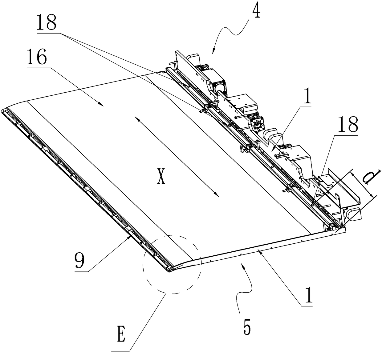
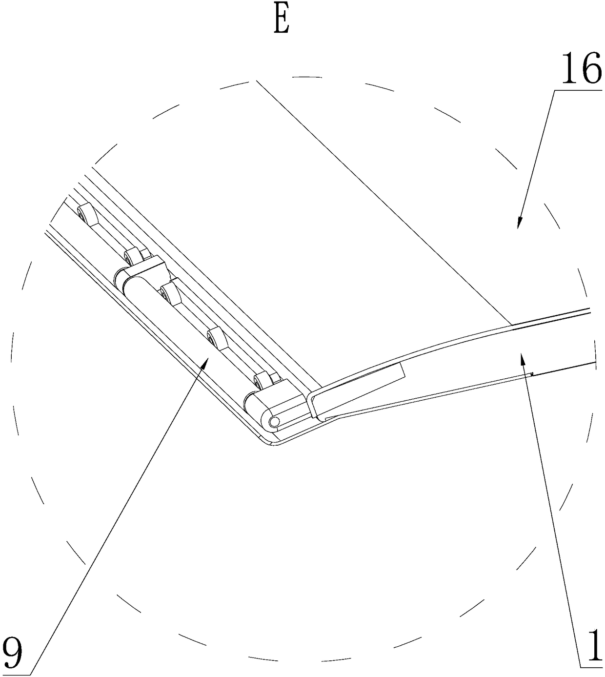
[0082] like Figure 16 to Figure 23 As shown in any view in , there are multiple flexible belts 2, and the multiple flexible belts 2 are sequentially arranged at intervals along the width direction X of the rack 1, and the equipment installation area 4 is located in the corresponding flexible belt 2 The corresponding upper rollers 6, lower rollers 7 and transfer drivers 8 are provided at the corresponding positions, and the corresponding front rollers 9 are provided at the corresponding positions of the flexible belts 2 in the working area 5.

[0083] Embodiment 1 as the transport driver 8:

[0084] like ...


PUM


Abstract

The invention discloses a transfer bed, which comprises a frame and a flexible belt. The bottom of the frame is provided with a running mechanism, and an equipment installation area and a working areaare arranged adjacently above the running mechanism. The transfer bed is characterized in that: an upper roller, a lower roller and a transfer drive are arranged in the equipment installation area. The upper roller and the lower roller are rotatably cooperated with the frame. A front roller is provided in the working area. One end of the flexible belt is wound around the upper roller, and the other end of the flexible belt is wound along the length of the front roller through the outer side wall of the front roller and then extends toward the lower roller to be retracted on the lower roller.The portion of the flexible belt adjacent to the front roller is inverted by the front roller to form a two-layer structure. The upper region of the upper flexible belt forms a transport space. The transfer drive rotates or advances the flexible belt along its length by driving the upper or lower roller.

Description

technical field [0001] The invention relates to the technical field of medical auxiliary equipment, in particular to a transfer bed. Background technique [0002] In medical work, it is often encountered that patients need to be transferred between different beds, such as between ordinary beds and operating room beds, between ordinary beds and testing room beds, between emergency beds and ordinary beds, etc. For patients with limited mobility, even critically ill patients who have lost consciousness, they can only rely on medical staff to carry them when they encounter the above-mentioned situations that need to be transported, and even experienced medical staff cannot avoid the existence of manual lifting. There is a risk of secondary injury to patients, so a transfer device for patients lying flat to transfer between different beds has been produced during the development of the industry. [0003] For example, the invention patent application whose patent name is a two-wa...

Claims


Application Information

Patent Timeline
Patent Type & Authority Applications(China)
IPC IPC(8): A61G7/10
CPCA61G7/1032A61G7/1065A61G7/1073
Inventor 王旭升王洪波桑凌峰石少华甘中学
Owner 浙江佑仁智能机器人有限公司
Why Eureka
Try Eureka