
Online detection method for optical fiber link of modular multilevel converter control system

A modular multi-level, control system technology, applied in electromagnetic wave transmission systems, transmission systems, electrical components, etc., can solve the problems of time-consuming, labor-intensive, secondary damage, etc., achieve low cost, avoid potential safety hazards, and be easy to implement Effect

Inactive Publication Date: 2020-09-29
NR ENG CO LTD +1
View PDF6 Cites 0 Cited by
  • Summary
  • Abstract
  • Description
  • Claims
  • Application Information

AI Technical Summary

Problems solved by technology

[0003] The current detection method is to manually perform spot checks or full inspections of optical fibers during power outage maintenance at the converter station. If the attenuation of the optical fiber is found to be too large, the spare core will be replaced, and if the optical transceiver module is found to be abnormal, the spare parts will be replaced. The manual detection process is not only time-consuming and labor-intensive , and there is a risk of secondary damage in the process of fiber detection, plugging and unplugging. A safer, more efficient and comprehensive fiber link detection method is urgently needed to conduct online health diagnosis of all fiber links and provide early warning during maintenance. It not only greatly improves the maintenance efficiency, but also avoids faulty operation of links with insufficient margin, ensuring the safe and stable operation of the system

Method used


Image

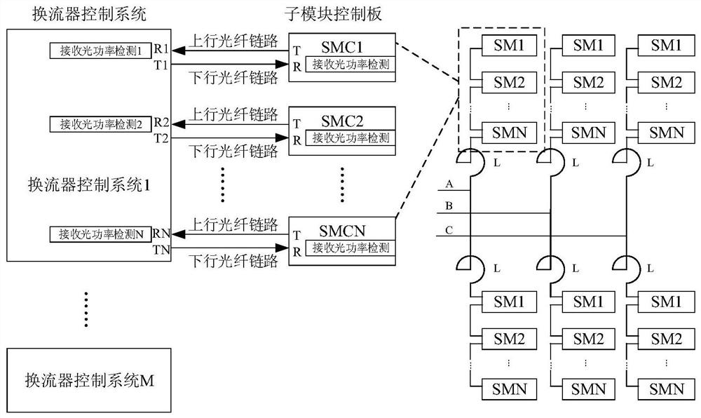
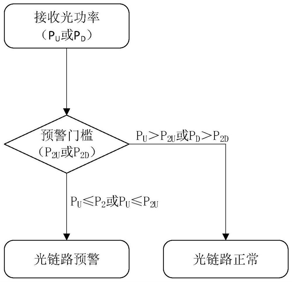
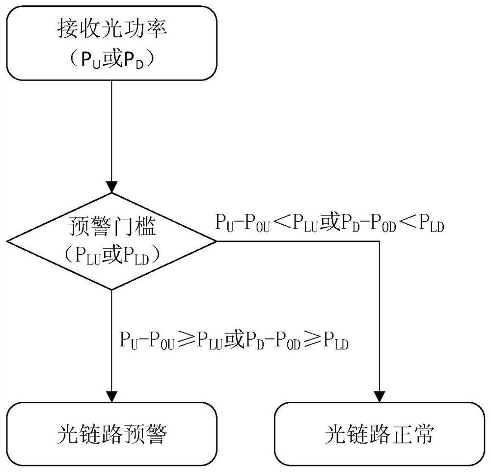
  • Online detection method for optical fiber link of modular multilevel converter control system
  • Online detection method for optical fiber link of modular multilevel converter control system
  • Online detection method for optical fiber link of modular multilevel converter control system

Examples


Embodiment Construction

[0018] The technical solutions and beneficial effects of the present invention will be described in detail below in conjunction with the accompanying drawings.

[0019] Such as figure 1 As shown, the present invention provides an embodiment of an online detection method for an optical fiber link in a modularized multilevel converter control system, including a converter control system and numerous sub-modules, and a converter control system and numerous sub-modules Communication via fiber optics. The converter control system includes multiple optical transceiver modules, each optical transceiver module includes one optical receiving R and one optical transmitting T, and each sub-module control board includes one optical receiving R and one optical transmitting T; the inverter control system The optical sending module T and the optical receiving module R of the sub-module control board are connected by optical fiber, which is defined as a downlink optical fiber link, and is us...


PUM


Abstract

The invention discloses an online detection method for an optical fiber link of a modular multilevel converter control system. The modular multilevel converter control system comprises a converter control system optical transceiver module, a sub-module control panel optical transceiver module and an optical fiber connected between the converter control system optical transceiver module and the sub-module control panel optical transceiver module. Receiving optical power detection circuits are configured on an optical transceiver module of a converter control system and an optical transceiver module of a sub-module control panel, and receiving optical power detection is carried out on an uplink optical fiber link and a downlink optical fiber link respectively. The online detection method comprises the following steps: summarizing received optical power information of all uplink and downlink optical fiber links, diagnosing and analyzing data according to a communication margin detection strategy and / or an optical fiber attenuation detection strategy, and early warning an unhealthy optical fiber link channel in advance. The online detection method can be used to solve a health diagnosis problem of the optical fiber link in a simplest, reliable and comprehensive mode.

Description

technical field [0001] The invention relates to an online detection method of an optical fiber link, in particular to the optical fiber link detection of a modular multilevel converter control system. Background technique [0002] High-voltage flexible DC transmission system is suitable for long-distance power transmission, wind power grid connection, submarine power transmission and other applications. Compared with AC transmission and traditional DC transmission, it has its unique advantages. In the high-voltage flexible DC transmission system based on modular multilevel converters, the converter valve is composed of many sub-modules (SM) cascaded, and the number of cascaded sub-modules in one bridge arm can reach hundreds, and the three-phase six bridges The number of sub-modules of the arm can reach thousands, and the higher the voltage level, the more the number of sub-modules. Each sub-module has a sub-module control board (SMC) for control and monitoring. Many sub-mo...

Claims


Application Information

Patent Timeline
Patent Type & Authority Applications(China)
IPC IPC(8): H04B10/079
CPCH04B10/07955
Inventor 李乐乐汪涛李汉杰虞晓阳张茂强王俊
Owner NR ENG CO LTD
Learn More