Stirring machine
A mixer and agitator shaft technology, applied in the field of mixing machinery, can solve the problems of unsatisfactory mixing effect of the mixer and discontinuous conveying materials, etc., and achieve the effect of improving the mixing effect, reasonable structure and sufficient mixing
- Summary
- Abstract
- Description
- Claims
- Application Information
AI Technical Summary
Problems solved by technology
Method used
Image

Examples
Embodiment Construction
[0018] In order to have a clearer understanding of the technical features, purposes and effects of the present invention, the specific implementation manners of the present invention will now be described in detail with reference to the accompanying drawings.
[0019] The purpose of the present invention is to design a continuous mixer with simple structure, sufficient stirring and efficient conveying.
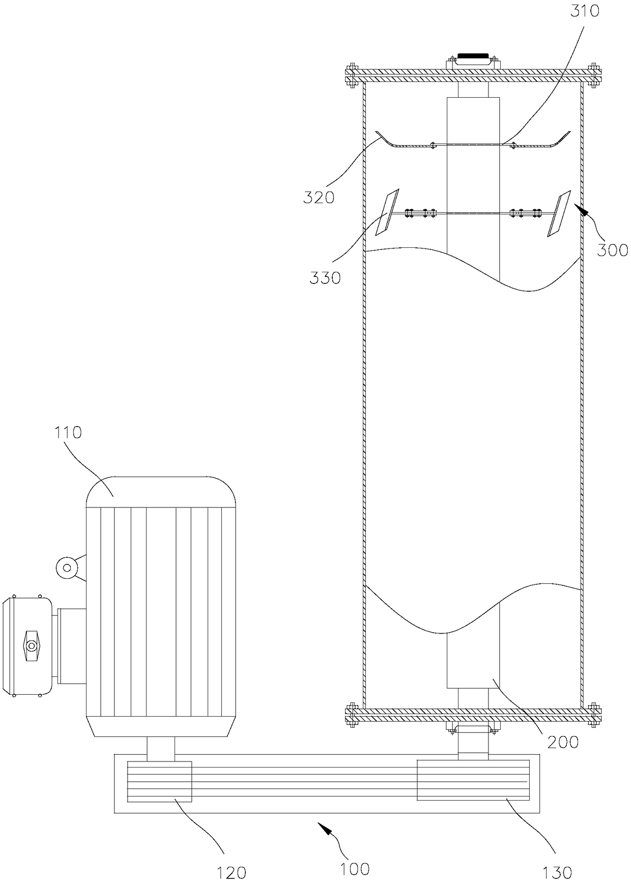
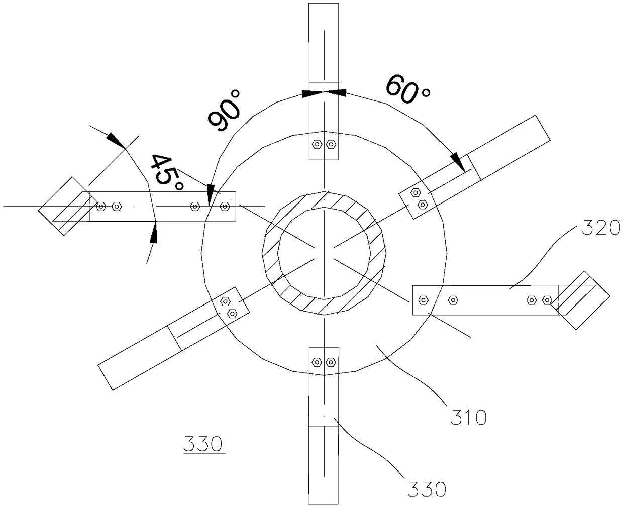
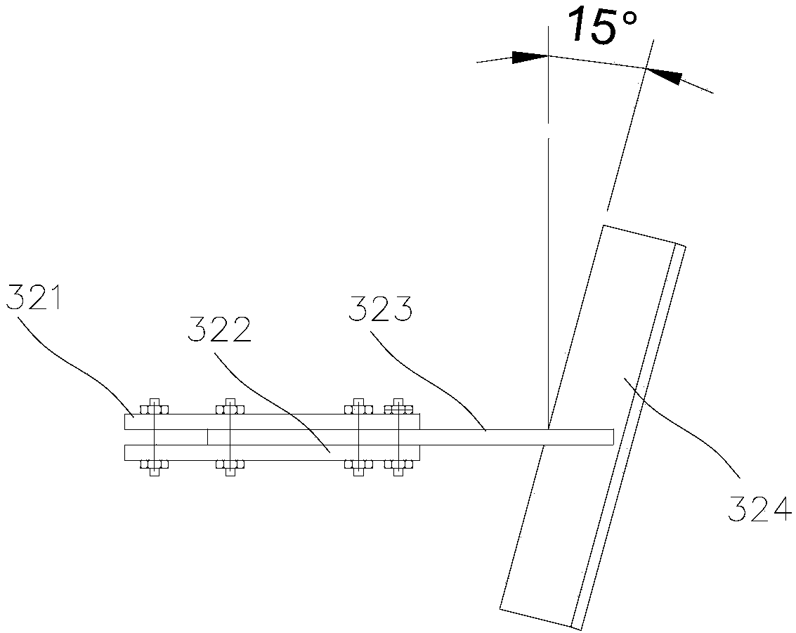
[0020] figure 1 It is a structural schematic diagram of a preferred embodiment of the mixer of the present invention, as figure 1 As shown, the mixer includes a power system 100 , a stirring shaft 200 driven by the power system 100 , and multiple sets of stirring blades 300 connected to the stirring shaft 200 . The stirring blade 300 includes a stirring paddle 310 , a rotary throwing blade 320 and a mixing blade 330 . The axial extension direction of the stirring shaft 200 is parallel to the direction of gravity.
[0021] The stirring paddle 310 is circular, sleeved in the ...
PUM
 Abstract
Description
Claims
Application Information
PatSnap Eureka turns technology decisions into work you can execute. Powered by our Innovation Knowledge Graph, it runs expert workflows across engineering, life sciences, materials and intellectual property. Get your review-ready output in minutes.


