
High pressure apparatus

A technology of high-pressure device and pressurizing device, which is applied to pressure vessels used in chemical processes, etc., can solve the problems of long-term use and complex structure, and achieve the effect of simple structure and convenient operation.

Inactive Publication Date: 2018-07-27
庞可 +2
View PDF3 Cites 1 Cited by
  • Summary
  • Abstract
  • Description
  • Claims
  • Application Information

AI Technical Summary

Problems solved by technology

[0002] Nowadays, a lot of processing and production needs the help of high-pressure gas, so it is necessary to use other pneumatic control elements to pressurize the high-pressure chamber for use, and the pressure that can be achieved by the pressurization devices currently on the market is generally relatively low , and the complex structure cannot be used for a long time under harsh conditions, so it is necessary to design a high-pressure device with a simple structure, which can achieve the required pressure and adapt to harsh conditions

Method used


Image

  • High pressure apparatus
  • High pressure apparatus
  • High pressure apparatus

Examples


Embodiment Construction

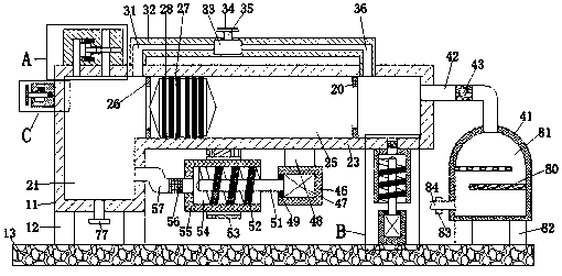
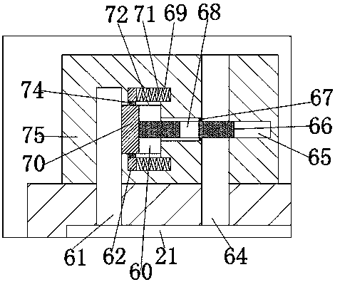
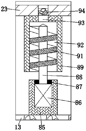
[0016] Such as Figure 1-Figure 4As shown, a high-voltage device of the present invention includes a supporting main structure I11, a pressurizing device arranged on the supporting main structure I11, and an inflatable device arranged on the upper end surface of the supporting main structure I11 near the left end surface. The control device and the electric control device arranged on the left end surface of the first supporting main structure 11, the pressurizing device includes an air compression chamber I21 arranged in the supporting main structure I11, and the supporting main structure I11 is close to The right end surface of the upper end surface is fixedly provided with a supporting body structure II23, and an air compression chamber II25 communicating with the air compression chamber I21 is arranged in the support body structure II23, and the air compression chamber II25 communicates with the air compression chamber II25. A first spacer 26 fixedly connected to the inner ...


PUM


Abstract

The invention discloses a high pressure apparatus, comprising supporting body structure I, compressing device arranged on the supporting body structure I, an inflation control device arranged on the upper end face, close to the left end face, of the supporting body structure I, and an electrical control device arranged on the left end face of the supporting body structure I; the compressing devicecomprises air compression chamber I arranged in the supporting body structure I; supporting body structure II is fixed to the right end face, close to the upper end face, of the supporting body structure I; air compression chamber II communicated with the air compression chamber I is arranged in the supporting body structure II; a first isolator fixedly connected to the inner wall of the air compression chamber II is arranged between the air compression chamber II and the air compression chamber I.

Description

technical field [0001] The invention relates to the technical field of high-pressure processing, in particular to a high-pressure device. Background technique [0002] Nowadays, a lot of processing and production needs the help of high-pressure gas, so it is necessary to use other pneumatic control units to pressurize the high-pressure chamber for use, and the pressure that can be achieved by the pressurization devices currently on the market is generally relatively low , and the complex structure cannot be used for a long time under harsh conditions, so it is necessary to design a high-pressure device with a simple structure, which can achieve the required pressure and adapt to harsh conditions. Contents of the invention [0003] The technical problem to be solved by the present invention is to provide a high-voltage device, which can solve the above-mentioned problems in the prior art. [0004] The present invention is achieved through the following technical solutions:...

Claims


Application Information

Patent Timeline
IPC IPC(8): B01J3/04
CPCB01J3/04
Inventor 庞可陈兆允陈招
Owner 庞可
Learn More