

Electromagnetic mold locking injection molding machine
A technology of injection molding machine and electromagnetic lock, applied in the field of injection molding machine, can solve the problems of slipping locking, breakage, weakening magnetic force, etc., and achieve the effect of improving the locking ability
- Summary
- Abstract
- Description
- Claims
- Application Information
AI Technical Summary
Problems solved by technology
Method used
Image

Examples
Embodiment Construction
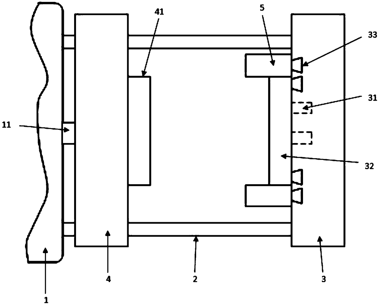
[0016] The specific embodiment of the present invention will be further described below in conjunction with accompanying drawing:
[0017] Such as figure 1 As shown, an electromagnetic clamping injection molding machine includes a frame 1, a guide post 2, a back seat 3 and a movable plate 4, and the frame 1 and the back seat 3 are provided with four guide posts 2 at a time, and the movable plate 4. The movable plate is threaded on the guide post 2 and the movable plate 4 is provided with a walking trolley corresponding to the guide post 2, so that the movable plate 4 can move back and forth along the guide post 2. The back seat 3 passes the bolt toward the movable plate 4 31 is equipped with a fixed mold 32, and the movable plate 4 is equipped with a movable mold 41 facing the side of the back seat. On the back seat 3 and above and below the bolts 31 are respectively provided with a plurality of card slots 33, and the card slots 33 pass through An electromagnet 5 is connected...
PUM
 Abstract
Description
Claims
Application Information