Determination method of airfoil line of wind power generation blade

A wind power generation blade and wind power blade technology are applied in wind power generation, wind turbines, and wind turbines in the same direction as the wind to achieve the effect of improving the utilization rate of wind energy.

Active Publication Date: 2019-10-22
NORTH CHINA ELECTRIC POWER UNIV (BAODING)
View PDF5 Cites 0 Cited by
  • Summary
  • Abstract
  • Description
  • Claims
  • Application Information

AI Technical Summary

Problems solved by technology

[0002] At present, the airfoils of wind power blades are still dominated by aviation airfoils. Although some special airfoils for wind power blades have been developed according to the characteristics of wind power blades, most of them are based on theoretical analysis, which still has a considerable impact on improving the utilization rate of wind energy. space

Method used


Image

  • Determination method of airfoil line of wind power generation blade
  • Determination method of airfoil line of wind power generation blade
  • Determination method of airfoil line of wind power generation blade

Examples


Embodiment 1

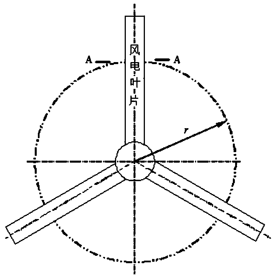
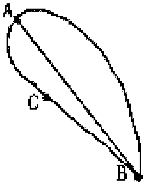
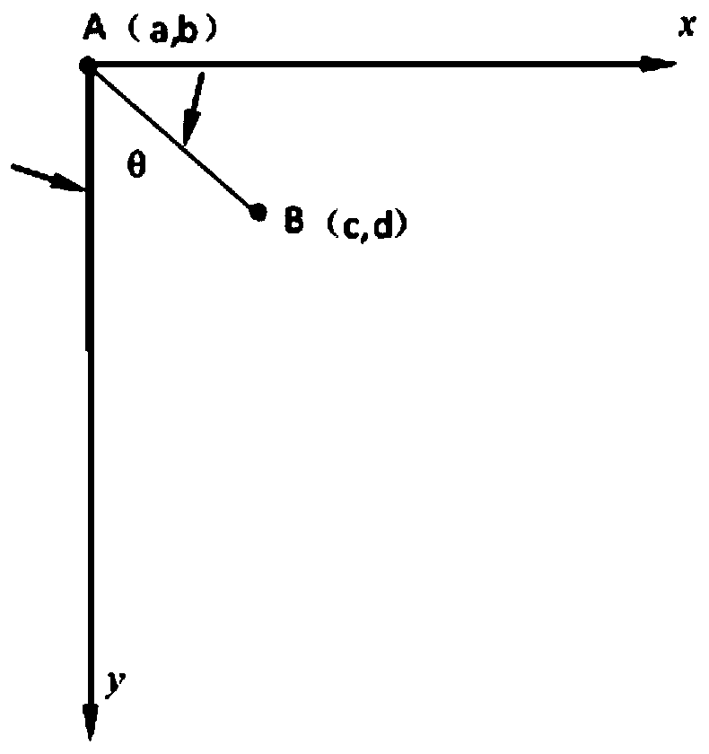
[0053] according to figure 1 , figure 2 Shown is a schematic diagram of a wind turbine. First build as image 3 In the Cartesian coordinate system of the airfoil of the wind power blade shown, it is assumed that the chord length AB of the airfoil on the blade whose distance from the rotation axis of the wind rotor is r is r, and the torsion angle is θ. The origin A slides to point B, if there is a curve Γ between points A and B, so that the time for the air mass to slide from point A to point B is the shortest, it means that the number of air masses sliding across the curve Γ within a certain period of time is large, That is, during this time, there are more air masses interacting with the curve Γ, so that the curve can obtain more energy from the air mass. Therefore, if the curve Γ is used as the airfoil line of the blade, The blade will be able to convert the kinetic energy of the air mass into the mechanical energy of the wind power blade;

[0054] 1) Determine the bla...

Embodiment 2

[0065] According to the traditional design method, the chord length of the blade airfoil at a certain radius of the wind rotor is l=2.38, and the twist angle θ=10.47o. Establish image 3 Shown coordinate system, wherein OB=l, is airfoil chord length, then the coordinate of point B is

[0066]

[0067] According to formula (19),

[0068]

[0069] Take D=1.17, substitute into formula (18), get airfoil line equation

[0070]

[0071] The airfoil line designed according to formula (20) (such as Figure 4 shown).


PUM


Abstract

The invention belongs to the technical field of wind power generation, and in particular relates to a method for determining an airfoil line of a wind power generation blade. First, establish the Cartesian coordinate system of the airfoil of the wind turbine blade, and set the chord length l and twist angle θ of the airfoil on the blade whose distance from the rotation axis of the wind rotor is r; the air mass slides from point A to point B. There is a curve Γ, so that the time for the air mass to slide from point A to point B is the shortest, which means that during this time, there are more air masses interacting with the curve Γ, so that the curve can obtain more from the air mass. Therefore, if this curve Γ is used as the airfoil line of the blade, the blade will be able to convert the kinetic energy of the air mass into the mechanical energy of the wind power blade. The invention can reduce the rated wind speed of the wind turbine by about 2 meters per second, and according to the difference of wind resources in rich and poor areas, it is preliminarily estimated that the average wind energy utilization rate can be increased by about 5%.

Description

technical field [0001] The invention belongs to the technical field of wind power generation, and in particular relates to a method for determining an airfoil line of a wind power generation blade. Background technique [0002] At present, the airfoils of wind power blades are still dominated by aviation airfoils. Although some special airfoils for wind power blades have been developed according to the characteristics of wind power blades, most of them are based on theoretical analysis, which still has a considerable impact on improving the utilization rate of wind energy. space. For this reason, we regard the flowing air as an air mass blowing to the wind turbine blades, and the time for an air mass to slide across the blade airfoil line is the shortest and in order to have as many air masses as possible acting on the blade airfoil line at the same time. The airfoil line is used as the boundary condition, and a method for determining the airfoil line of a wind power blade ...

Claims


Application Information

Patent Timeline
Patent Type & Authority Patents(China)
IPC IPC(8): F03D1/06
CPCF03D1/0675Y02E10/72
Inventor 张照煌穆罕默德阿珂王磊宋玉旺
Owner NORTH CHINA ELECTRIC POWER UNIV (BAODING)
Why Eureka
Try Eureka