Layered fan wind wheel and wind turbine adopting layered fan wind wheel

A layered, wind wheel technology, applied in the field of wind energy utilization, wind machinery and wind power generation, can solve the problems of low wind energy utilization efficiency at the blade root, high start-up wind speed, and decreased wind resistance of the fan, so as to reduce weight and improve Effect of power generation efficiency and length increase

Pending Publication Date: 2017-06-30
孟英志
View PDF0 Cites 0 Cited by
  • Summary
  • Abstract
  • Description
  • Claims
  • Application Information

AI Technical Summary

Problems solved by technology

[0002] At present, most horizontal axis propeller wind turbines have a 2-blade or 3-blade structure, and the blades are installed on the generator shaft or hub to form a wind rotor. This structure can optimize the rotation speed of the wind rotor, and its shortcomings The starting wind speed and the rated wind speed are high, and the wind energy utilization efficiency at the root of the blade is very low. In order to meet the requirements of the low wind speed wind field, the length of the blade needs to be continuously increased. After increasing the length of the blade, the fan’s ability to resist strong wind will be reduced. Therefore, it is necessary to invent a wind turbine that can reduce the starting wind speed or the rated wind speed, start with the breeze and can resist strong winds while improving the wind energy utilization efficiency at the blade root

Method used


Image

  • Layered fan wind wheel and wind turbine adopting layered fan wind wheel
  • Layered fan wind wheel and wind turbine adopting layered fan wind wheel
  • Layered fan wind wheel and wind turbine adopting layered fan wind wheel

Examples


Embodiment 1

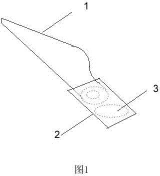
[0067] Such as figure 1 as shown, figure 1 It is a schematic diagram of the structure principle of the horizontal axis fan blade of the present invention; an extension device 2 is installed at the root of the blade 1, and one or more closed space devices 3 are installed inside the extension device 2, and the closed space device 3 is a rubber sealed bag or plastic sealed bag full of helium, which can replace or partially replace the original inner filler such as balsa wood or foam material or ribs. When the blade is running, the rubber sealing bag or plastic sealing bag generates upward buoyancy in the extension device 2, and holds the inner wall of the extension device 2, which can offset a part of the gravity of the extension device 2, reduce the overall weight of the blade, and reduce the motion generated Vibration, improve power generation efficiency. The shape of the extension device 2 matches the root of the blade 1 .

Embodiment 2

[0069] Such as figure 2 --9, figure 2 It is a schematic diagram of the front view of the structure principle of the horizontal axis fan rotor of the present invention; image 3 It is a schematic diagram of the left view of the structure principle of the horizontal axis fan rotor of the present invention; the top view is common knowledge and is omitted. In this embodiment, an extension device 2 is installed outside the hub 7 of the horizontal axis wind wheel. The extension device 2 is ellipsoidal or semi-ellipsoidal or any shape that can help wind blow to the blade. 1 or / and 4 are installed on the extension device 2 . One or more closed space devices 3 are installed inside the extension device 2, and the closed space devices 3 are rubber sealed bags or plastic sealed bags filled with helium, which can replace or partially replace the original internal filling Such as balsa wood or foam or ribs.

[0070] Figure 4 It is a front view schematic diagram of another structural...

Embodiment 3

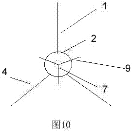
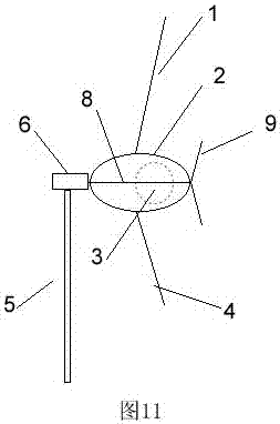
[0074] Such as Figure 10 , 11 as shown, Figure 10 It is a front view schematic diagram of another structural principle of the horizontal axis fan rotor of the present invention; Figure 11 It is a schematic diagram of the left view of another structural principle of the horizontal axis fan rotor of the present invention; the top view is common knowledge and is omitted.

[0075] In this embodiment, the extension device 2 can replace the role of the hub, the extension device 2 is an ellipsoidal or part ellipsoidal or spherical or part spherical structure; the extension device 2 is installed on the fan shaft 8, on the In the structure of the extension device 2, a group of long fan blades 1 or 4 are installed, and a group of short fan blades 9 are installed in front of the extension device 2.

[0076] In this embodiment, 3 short fan blades are installed, and the length of the short fan blade 9 is less than the long fan blade 1 or 4; the small wind wheel can reduce the rated w...


PUM


Abstract

The invention provides a layered fan wind wheel and a wind turbine adopting the layered fan wind wheel. Through the layered fan wind wheel, wind energy on the root portions of blades can be effectively utilized, the starting wind speed and the rated wind speed of a fan are decreased, the power generation efficiency of the fan is improved, and accordingly the purpose of starting the fan under the breeze condition is achieved; meanwhile, through the advantages of the fan wind wheel provided with a lengthening device, the diameter of the wind wheel or the lengths of the blades can be effectively increased, the ultra-large blades with the diameters being 200 m or over or with the lengths being 100 m or over can be provided, and a wind power generator with the power being 10 MW or over can be provided; and furthermore, the layered fan wind wheel and the wind turbine adopting the layered fan wind wheel have the capacity to resist typhoons.

Description

technical field [0001] The invention belongs to the technical field of wind energy utilization, and is especially applicable to the technical fields of wind power machinery and wind power generation. Background technique [0002] At present, most horizontal axis propeller wind turbines have a 2-blade or 3-blade structure, and the blades are installed on the generator shaft or hub to form a wind rotor. This structure can optimize the rotation speed of the wind rotor, and its shortcomings The starting wind speed and the rated wind speed are high, and the wind energy utilization efficiency at the blade root is very low. In order to meet the requirements of the low wind speed wind field, the length of the blade needs to be continuously increased. After increasing the blade length, the fan’s ability to resist strong winds will be reduced. Therefore, it is very necessary to invent a wind-driven generator that can reduce the starting wind speed or the rated wind speed, start with a...

Claims


Application Information

Patent Timeline
Patent Type & Authority Applications(China)
IPC IPC(8): F03D1/06F03D7/02
CPCF03D1/065F03D1/0675F03D7/0236F05B2240/312Y02E10/72
Inventor 孟英志
Owner 孟英志
Why Eureka
Try Eureka