Hydraulic flow distributing system for distributing pressure proportion randomly

A technology of arbitrary distribution and diversion system, which is applied in the field of hydraulic systems, can solve the problems of narrow application range, high cost, and inability to realize other pressure ratios, etc., and achieve the effect of wide application range and low cost

Inactive Publication Date: 2018-07-27
ANHUI UNIVERSITY OF TECHNOLOGY AND SCIENCE
View PDF10 Cites 9 Cited by
  • Summary
  • Abstract
  • Description
  • Claims
  • Application Information

AI Technical Summary

Problems solved by technology

[0004] Now generally in order to achieve a specific pressure ratio parameter, it is necessary to design a corresponding hydraulic system, that is, a hydraulic system can only achieve a specific pressure ratio,

Method used


Image

  • Hydraulic flow distributing system for distributing pressure proportion randomly
  • Hydraulic flow distributing system for distributing pressure proportion randomly
  • Hydraulic flow distributing system for distributing pressure proportion randomly

Examples


Embodiment Construction

[0016] The technical solutions in the embodiments of the present invention will be clearly and completely described below with reference to the accompanying drawings in the embodiments of the present invention. Obviously, the described embodiments are only a part of the embodiments of the present invention, but not all of the embodiments. Based on the embodiments of the present invention, all other embodiments obtained by those of ordinary skill in the art without creative efforts shall fall within the protection scope of the present invention.

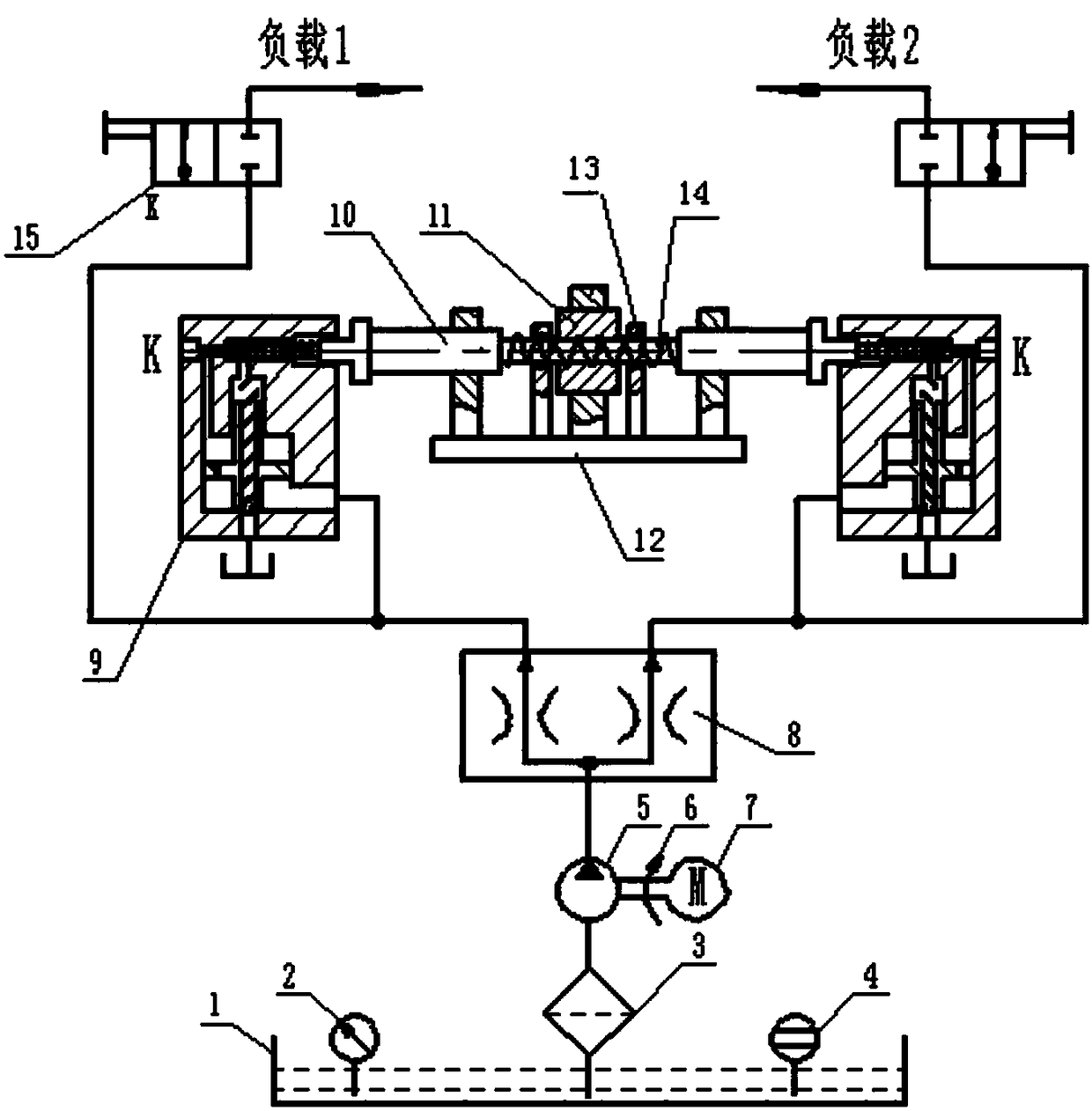
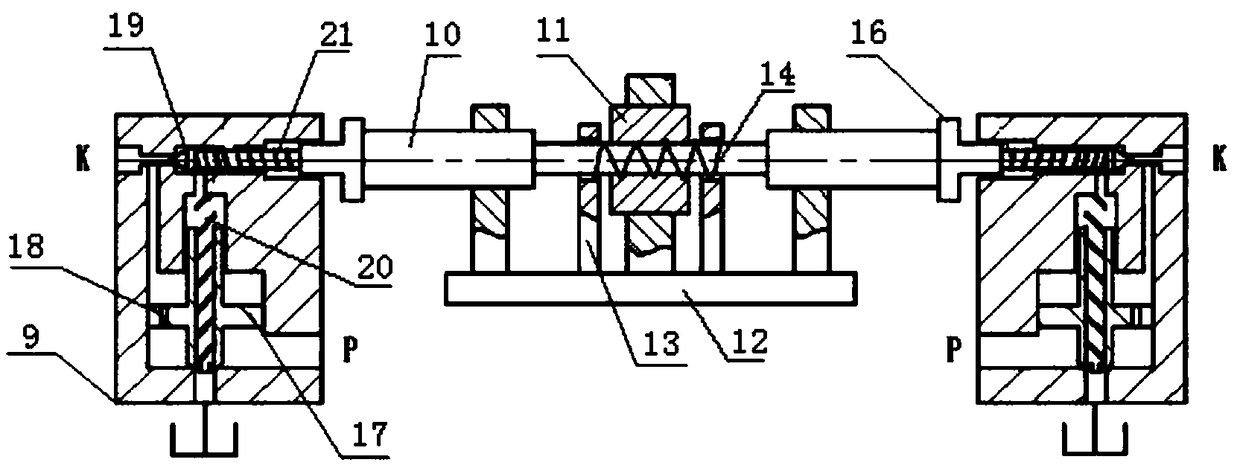
[0017] like figure 1 and figure 2 As shown, a hydraulic shunt system with an arbitrary distribution pressure ratio includes an oil tank 1, a shunt valve 8, a quantitative pump 5, an electric motor 7 and a pressure regulating unit, and the oil tank 1, the input end of the shunt valve 8, and the electric motor are all connected with the quantitative pump 5. , the coupling 6 is connected between the motor 7 and the quantitative pump 5,...


PUM


Abstract

The invention discloses a hydraulic flow distributing system for distributing the pressure proportion randomly. The hydraulic flow distributing system comprises an oil tank, a split-flow valve, a metering pump, a motor and a pressure regulating unit. The oil tank, the input end of the split-flow valve and the motor are connected with the metering pump, and a coupler is connected between the motorand the metering pump. The two output ends of the split-flow valve are connected with a pilot type overflow valve and a reversing valve correspondingly. The pressure regulating unit comprises a rack,a lead screw and a pilot type overflow valve. The two pilot type overflow valves are symmetrically arranged on the two sides of the rack, and the two ends of the lead screw are connected with the pilot type overflow valve correspondingly. The lead screw comprises a screw rod and a nut spirally connected to the screw rod. According to the hydraulic flow distributing system, the ball screw is adopted as an actuating element, the pretightening force of springs of the two pilot type overflow valves is controlled by rotating the nut on the ball screw, then the pressure of the overflow valve is regulated to control the pressure of two branches, and finally distribution of any pressure proportion is achieved. The hydraulic flow distributing system is wide in application range and low in cost.

Description

technical field [0001] The invention relates to a hydraulic system, in particular to a hydraulic shunt system that can distribute pressure proportionally at will. Background technique [0002] Pressure control valves are mainly divided into relief valves, pressure reducing valves and sequence valves according to their functional purposes. The relief valve can control the hydraulic system to maintain a constant state when the set pressure is reached. When the pressure of the hydraulic system rises to exceed the limit value of the relief valve, the valve port will be opened for relief to ensure the safety of the hydraulic system. [0003] The pilot-operated relief valve is composed of a pilot valve and a main valve. The function of the pilot valve is to relieve pressure. Therefore, the stable pressure of the pilot-operated relief valve is controlled by the pilot valve and the pressure regulating spring. The preload force of the spring can be adjusted by pressing the spring, a...

Claims


Application Information

Patent Timeline
IPC IPC(8): F15B13/02F15B21/04F16K17/30
CPCF15B13/022F15B21/041F15B2211/615F16K17/30
Inventor 王幼民李亚飞唐铃凤随和张振蒋秦帅郭富城谢鹏飞
Owner ANHUI UNIVERSITY OF TECHNOLOGY AND SCIENCE
Why Eureka
Try Eureka