
Cooling equipment for project

A technology of cooling equipment and engineering, applied in the field of construction, can solve the problems of slow cooling speed and difficulty in meeting engineering needs.

Inactive Publication Date: 2018-07-27
桐乡市梧桐春秋机械维修部
View PDF5 Cites 0 Cited by
  • Summary
  • Abstract
  • Description
  • Claims
  • Application Information

AI Technical Summary

Problems solved by technology

[0004] In the project, it is necessary to cool the water to meet the project requirements, but the existing water cooling generally adopts static cooling, so the cooling speed of the water is slow, and it is difficult to meet the project requirements

Method used


Image

  • Cooling equipment for project

Examples


Embodiment Construction

[0016] In order to make the technical means, creative features, goals and effects achieved by the present invention easy to understand, the present invention will be further elaborated below in conjunction with specific embodiments and accompanying drawings, but the following embodiments are only preferred embodiments of the present invention, not all . Based on the examples in the implementation manners, other examples obtained by those skilled in the art without making creative efforts all belong to the protection scope of the present invention.

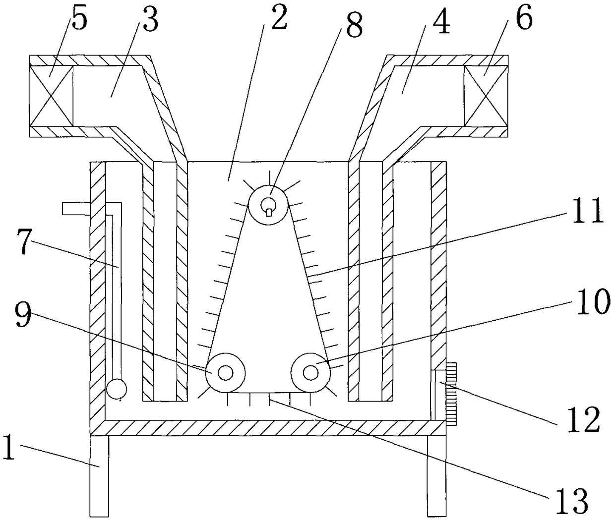
[0017] Such as figure 1 As shown, a kind of engineering cooling equipment includes a fixed bracket 1, the upper end of the fixed bracket 1 is connected to the device casing 2, and the device casing 2 is provided with a cooling pipe A3 on one side and a cooling pipe B4 on the other side, wherein The exhaust ends of the cooling pipe A3 and the cooling pipe B4 are located below the water surface, the air inlet end of the cooling pipe...


PUM


Abstract

Cooling equipment for the project comprises a fixing support. The upper end of the fixing support is connected with a device shell. A cooling pipe A is arranged on one side of the device shell, and acooling pipe B is arranged on the other side of the device shell. A heat dissipation draught fan A is arranged at the air inlet end of the cooling pipe A, and a heat dissipation draught fan B is arranged at the air inlet end of the cooling pipe B. A temperature sensor is arranged on one side of the device shell. A drive roller A, a drive roller B and a drive roller C are arranged in the device shell, a conveying belt is wound around the outer sides of the drive roller A, the drive roller B and the drive roller C, and the outer side of the conveying belt is provided with a plurality of stirringblades. When the cooling equipment is used, water is drained into the device shell, cold air is generated by the heat dissipation draught fan A and the heat dissipation draught fan B in the flowing process to dissipate heat of water in the water flow process, the stirring blades can further stir and dissipate heat of the water, accordingly, the water can be rapidly cooled, and the project need ismet.

Description

technical field [0001] The invention relates to the technical field of construction, in particular to engineering cooling equipment. Background technique [0002] Engineering is the application of science and mathematics by which the properties of matter and energy in nature can be manipulated through structures, machines, products, systems and processes in the shortest time and with the least amount of manpower Something efficient, reliable, and useful to humans. The general term for various disciplines formed by applying the theories of natural science to specific industrial and agricultural production sectors. [0003] Construction engineering refers to the engineering entity formed through the construction of various housing buildings and their ancillary facilities and the installation activities of supporting lines, pipelines and equipment. Among them, "housing construction" refers to projects that have roofs, beams, walls, foundations, and can form internal spaces to...

Claims


Application Information

Patent Timeline
Patent Type & Authority Applications(China)
IPC IPC(8): F25D1/00F25D1/02
CPCF25D1/00F25D1/02
Inventor 不公告发明人
Owner 桐乡市梧桐春秋机械维修部
Learn More