Bridge routing inspection system

A technology for inspection systems and bridges, applied in measuring devices, elastic testing, instruments, etc., can solve the problems of low reliability, single means, low efficiency, etc., and achieve the effects of high reliability, high flexibility and high efficiency

Inactive Publication Date: 2018-07-27
ZHUZHOU TIMES ELECTRONICS TECH CO LTD
View PDF17 Cites 25 Cited by
  • Summary
  • Abstract
  • Description
  • Claims
  • Application Information

AI Technical Summary

Problems solved by technology

[0015] In view of this, the purpose of the present invention is to provide a bridge inspection system to solve the te

Method used


Image

  • Bridge routing inspection system
  • Bridge routing inspection system
  • Bridge routing inspection system

Examples


Embodiment 1

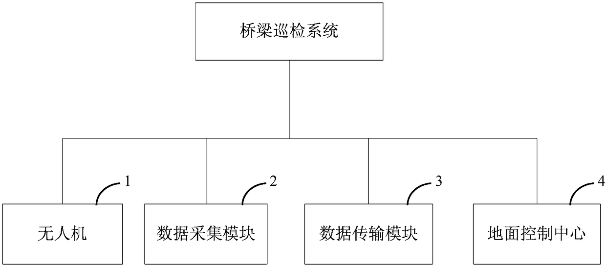
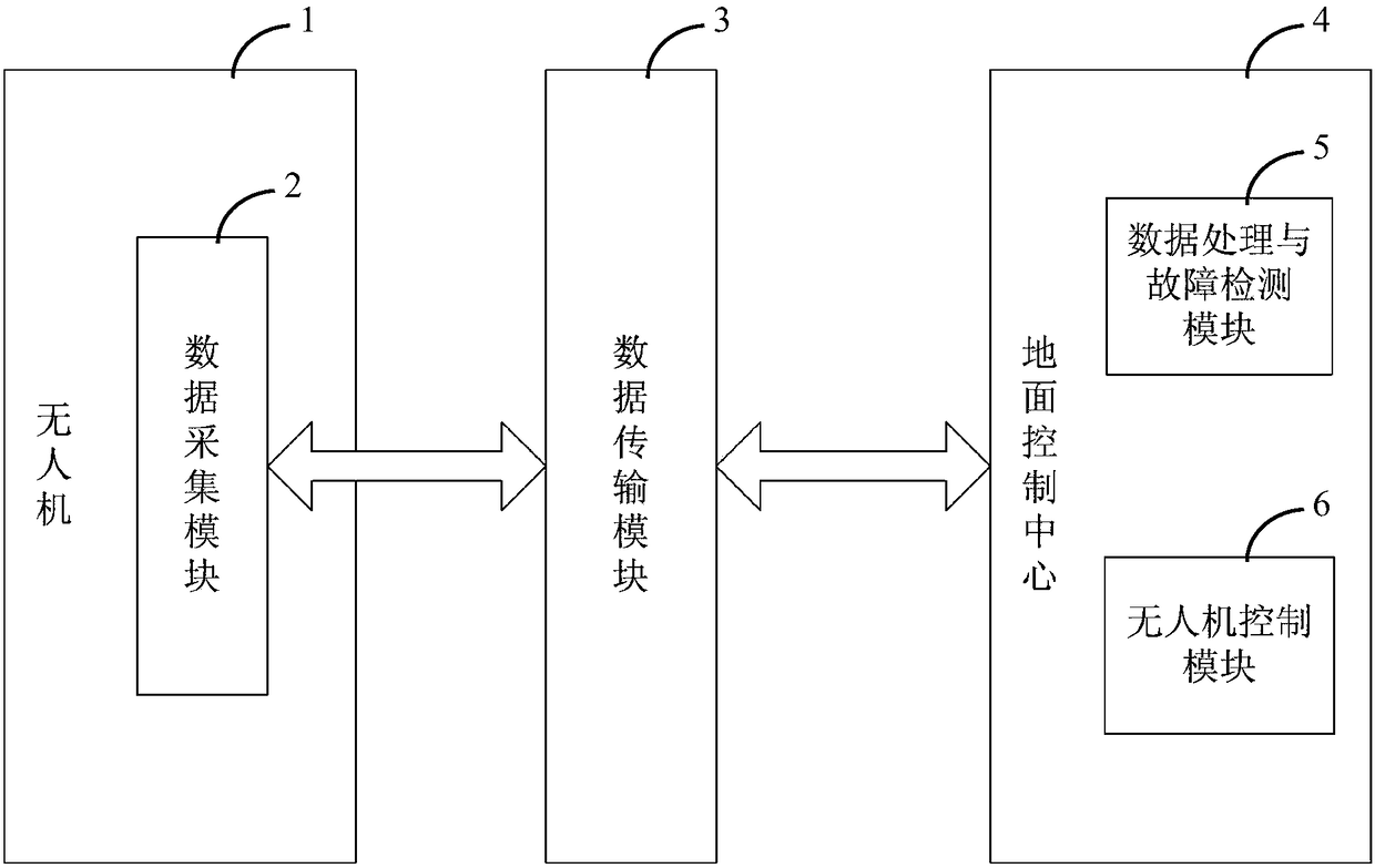
[0049] as attached figure 1 And attached figure 2 As shown, a specific embodiment of the bridge inspection system of the present invention is used for bridge 7 inspections, including: UAV 1, data transmission module 3, ground control center 4, and data carried on UAV 1 Acquisition module 2. The UAV 1 can be in the form of a fixed-wing UAV, a multi-rotor UAV or an unmanned helicopter. Wherein, the data collection module 2 includes various sensors mounted on the UAV 1 for collecting on-site information of the bridge. The data acquisition module 2 further includes a laser three-dimensional scanner 21 and a ground radar 22 . The UAV 1 collects on-site data of the bridge 7 through a laser three-dimensional scanner 21 and a ground radar 22 . The on-site data collected by the drone 1 is sent to the ground control center 4 through the data transmission module 3 . The data processing and fault detection module 5 of the ground control center 4 processes the laser three-dimensional...

Embodiment 2

[0062] as attached Figure 8 As shown, a specific embodiment of a bridge inspection method based on the system described in Embodiment 1, comprising the following steps:

[0063] S101) The unmanned aerial vehicle 1 collects the field data of the bridge 7 through the laser three-dimensional scanner 21 and the ground radar 22 carried on it;

[0064] S102) The on-site data collected by the UAV 1 is sent to the ground control center 4 through the data transmission module 3;

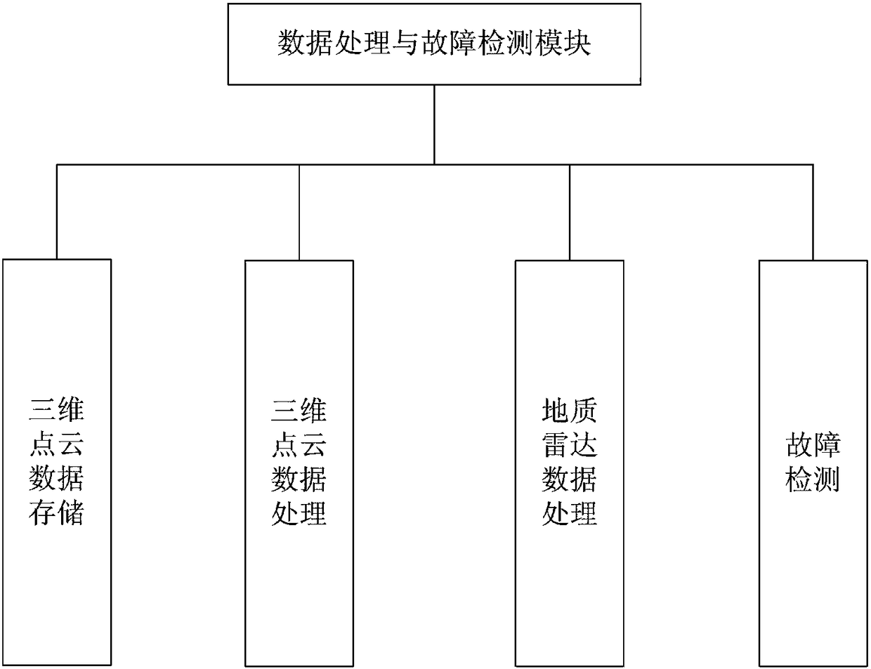
[0065] S103) The data processing and fault detection module 5 of the ground control center 4 processes the laser three-dimensional scanning data collected by the laser three-dimensional scanner 21 to complete the three-dimensional modeling of the detected area of ​​the bridge 7, and at the same time, the radar echo collected by the ground radar 22 wave data processing;

[0066] S104) The data processing and fault detection module 5 detects the defect and the position of the defect of the bridge 7 by analyzi...


PUM


Abstract

The invention discloses a bridge routing inspection system, which comprises an unmanned aerial vehicle, a data transmission module, a ground control center and a data acquisition module carried on theunmanned aerial vehicle. The data acquisition module comprises a laser three-dimensional scanner and a geological radar. The unmanned aerial vehicle collects field data of a bridge through the laserthree-dimensional scanner and the geological radar. Field data collected by the unmanned aerial vehicle are sent to the ground control center through the data transmission module. The data processingand fault detection module of the ground control center processes laser three-dimensional scanning data collected by the laser three-dimensional scanner, so that the three-dimensional modeling of thedetected area of the bridge is completed. Meanwhile, radar echo data collected by the geological radar are processed. The data processing and fault detection module analyzes three-dimensional modelingand radar echo data, detects the defect of the bridge and the position of the defect of the bridge. According to the invention, the technical problem that an existing bridge inspection mode is high in cost, low in efficiency, single in means and low in reliability can be solved.

Description

technical field [0001] The invention relates to the field of engineering measurement, in particular to a bridge inspection system, in particular to an inspection system applied to railway bridges. Background technique [0002] As of 2013, the total mileage of domestic railways has exceeded 100,000 kilometers, and the operating mileage of high-speed rail has reached nearly 10,000 kilometers. Calculated based on the proportion of bridges accounting for 52% of the lines, there are about 5,000 kilometers of high-speed rail bridges in my country. For example, the accumulative length of the Beijing-Tianjin intercity bridge accounts for 86.6% of the total length of the main line, 80.5% for the Beijing-Shanghai high-speed railway, 94.0% for the Guangzhou-Zhuhai intercity bridge, 48.5% for the Wuhan-Guangzhou Railway, and 74.3% for the Harbin-Dalian Railway. According to the "Medium and Long-term Railway Network Planning", the development of my country's high-speed railways focuses o...

Claims


Application Information

Patent Timeline
IPC IPC(8): G01M5/00
CPCG01M5/0008G01M5/0033G01M5/0075
Inventor 李懿颜琼陈平松王文昆李佳
Owner ZHUZHOU TIMES ELECTRONICS TECH CO LTD
Why Eureka
Try Eureka