Arc wind tunnel test assessment method for non-ablative thermal protection material/structure

A heat protection material and wind tunnel test technology, which is applied in the testing of machines/structural components, aerodynamic tests, measuring devices, etc., can solve the problems of untestable state deviation, lack of effective means, electrode ablation, etc., and achieve saving Effects of test cost and period, reduction of test times, and improvement of test accuracy

Active Publication Date: 2018-07-27
BEIJING AEROSPACE TECH INST
View PDF7 Cites 9 Cited by
  • Summary
  • Abstract
  • Description
  • Claims
  • Application Information

AI Technical Summary

Problems solved by technology

[0004] However, due to the long-term operation of the electrode during the arc wind tunnel test, ablation will occur, which will cause fluctuations in the flow state. The fluctuation of the enthalpy value of the same train is about 5%, and the fluctuation range of the enthalpy value between different trains is about 10%. When the enthalpy is low, this fluctuation will cause a temperature difference of about 200°C on the surface of the test piece, and when the enthalpy is high, the above-mentioned enthalpy difference has a greater influence on the temperature
In addition, in order to ensure that the nozzle can withstand the effect of high-temperature airflow for a long time, it is necessary to design a water-cooling system to cool the nozzle, and the water-cooling system will also take away the high-temperature gas near the wall of the nozzle while cooling the nozzle. energy, resulting in reduced flow status
However, the fluctuation of the test state caused by electrode ablation and the influence of the cooling of the nozzle on the flow state are affected by many factors such as the test state, electrode use state, cooling water flow rate, temperature, etc. At present, there is no effective means, and it is impossible to give the test before the test. state deviation

Method used


Image

  • Arc wind tunnel test assessment method for non-ablative thermal protection material/structure
  • Arc wind tunnel test assessment method for non-ablative thermal protection material/structure
  • Arc wind tunnel test assessment method for non-ablative thermal protection material/structure

Examples


Embodiment Construction

[0025] In order to illustrate the present invention more clearly, the present invention will be further described below in conjunction with preferred embodiments and accompanying drawings. Similar parts in the figures are denoted by the same reference numerals. Those skilled in the art should understand that the content specifically described below is illustrative rather than restrictive, and should not limit the protection scope of the present invention.

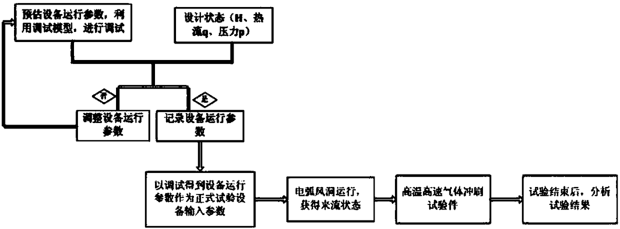
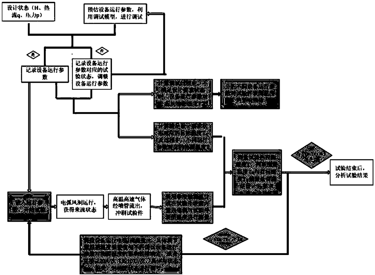
[0026] Such as image 3 As shown, the arc wind tunnel test assessment method of a non-ablative thermal protection material / structure provided in this embodiment includes the following steps:

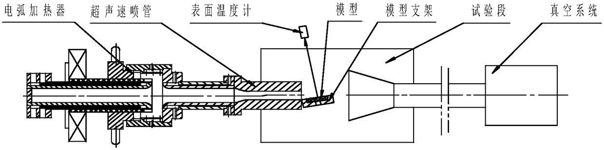
[0027] Carry out test state debugging: According to the design state, estimate the operating parameters of the equipment, including current I, voltage U, hot gas flow rate m 热 and cold air flow m 冷 ;Take the non-ablative thermal protection material / structure as the test piece, use a physical model with the same size as the test pie...


PUM


Abstract

The invention discloses an arc wind tunnel test assessment method for a non-ablative thermal protection material/structure. The method comprises: conducting test state debugging; calculating a targettemperature of a surface of a test piece corresponding to an inflow state obtained by debugging; conducting a formal test; and adjusting operating parameters of equipment according to a temperature measurement result of the surface temperature of the test piece during the formal test. The method of the invention realizes real-time adjustment and precise control of the inflow state during the test.

Description

technical field [0001] The invention relates to the technical field of thermal protection materials / structures. More specifically, it relates to an arc wind tunnel test method for non-ablative thermal protection materials / structures. Background technique [0002] Thermal protection materials / structures for hypersonic vehicles need to carry out ground arc wind tunnel tests to assess the high temperature resistance and ablation resistance of materials / structures. use as figure 1 When the arc wind tunnel test device shown in the arc wind tunnel test is carried out, the air flow is heated by the arc and flows into the mixing chamber, where it is mixed with cold air. After passing through a specific nozzle, it enters the test section at high temperature and high speed, and the test piece is subjected to Flush, and enter the vacuum system through the back-end pipeline (diffuser, cooler, etc.), and then pumped out into the atmosphere by the vacuum pump. [0003] Such as figure...

Claims


Application Information

Patent Timeline
Patent Type & Authority Applications(China)
IPC IPC(8): G01M9/04G01M9/06
CPCG01M9/04G01M9/065
Inventor 宋月娥陈晓娜李晶马寅魏曹杰张帆王洋陈凯陈智铭
Owner BEIJING AEROSPACE TECH INST
Why Eureka
Try Eureka