
Arc detection and prevention in a power generation system

An electrical system, arc technology, applied in the monitoring of photovoltaic systems, photovoltaic power generation, test circuits, etc., can solve problems such as increasing the risk of fire, increasing operating and/or insurance costs, and achieving prevention of transmission errors and high accuracy. , the effect of prolonging the service life

Active Publication Date: 2018-07-27
SOLAREDGE TECH LTD
View PDF15 Cites 4 Cited by
  • Summary
  • Abstract
  • Description
  • Claims
  • Application Information

AI Technical Summary

Problems solved by technology

Arcing in photovoltaic systems also increases the risk of fire, thereby increasing operating and / or insurance costs for facilities with photovoltaic systems

Method used


Image

  • Arc detection and prevention in a power generation system
  • Arc detection and prevention in a power generation system
  • Arc detection and prevention in a power generation system

Examples


Embodiment Construction

[0046] Reference will now be made in detail to the embodiments, examples of which are illustrated in the accompanying drawings, wherein like reference numerals refer to like elements throughout. The embodiments are described below to explain the present disclosure by referring to the figures.

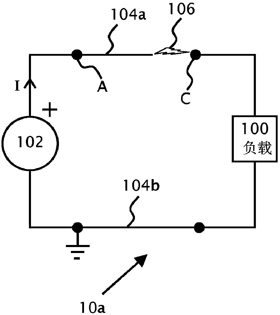
[0047] refer to Figure 1a , which shows series arcing 106 in circuit 10a according to the background art. exist Figure 1a 1, a direct current (DC) power source 102 provides power between power lines 104a and 104b. Power line 104b is shown at ground potential. The load 100 connects the power line 104b to the power line 104a. Series arcing may occur in any part of the circuit 10a, such as in the power lines 104a, 104b or inside the load 100 or power source 102. Shown is an instance 106 of a disconnection or poor connection between points C and A in power line 104a, which results in series arcing. Typically, if a series arc 106 can be detected, a circuit breaker (not shown) at the ...


PUM


Abstract

The invention provides methods for arc detection in a system including one or more photovoltaic generators, one or more photovoltaic power devices and a system power device and / or a load connectible to the photovoltaic generators and / or the photovoltaic power devices. The methods may measure voltage, current, and / or power delivered to the load or system power device, and the methods may measure voltage noise or current noise within the photovoltaic system. The methods may periodically, and / or in response to detecting noise, reduce an electrical parameter such as current or voltage in order toextinguish an arc. The methods may compare one or more measurements to one or more thresholds to detect arcing, and upon a comparison indicating that arcing is or was present, an alarm condition may be set.

Description

[0001] Cross References to Related Applications [0002] This application is a foreign convention application of U.S. Application No. 15 / 407,881, filed January 17, 2017, which is a continuation-in-part (CIP) of U.S. Application No. 13 / 290,528, filed November 7, 2011, so The above US application claims priority to UK application GB1018872.0, filed 9 November 2010, all of which are hereby incorporated by reference in their entirety. U.S. Application No. 15 / 407,881 is also a continuation-in-part (CIP) application of U.S. Application No. 15 / 250,068, filed August 29, 2016, which claims U.S. Application No. 62 / 318,303, filed April 5, 2016 Provisional Patent Application and priority to U.S. Provisional Patent Application No. 62 / 341,147, filed May 25, 2016, all of which are incorporated herein by reference in their entirety. U.S. Application No. 15 / 407,881 also claims priority to U.S. Provisional Patent Application No. 62 / 395,461, filed September 16, 2016, which is hereby incorporated...

Claims


Application Information

Patent Timeline
IPC IPC(8): G01R31/14G01R31/12H02S50/10
CPCH02S50/10H02J3/381H02J2300/24H02H1/0015H02H7/20H02J1/12H02J3/46H02S10/00H02S40/32H02S40/34H02S40/36H02S50/00G01R31/12Y02E10/56
Inventor 伊兰·约瑟考维奇G·塞拉M·盖兹特Y·戈林大卫·布拉金斯基L·汉德尔斯曼M·阿德斯特亚基尔·洛温斯腾察希·格罗文斯基纳达夫·贝尔科维奇罗恩·纽曼A·菲谢尔夫
Owner SOLAREDGE TECH LTD
Learn More