Wire connecting wire clamp
A wire connection and wire clip technology, which is applied in the direction of conductive connection, connection, and electrical component connection, can solve the problems of laborious, time-consuming, and expensive wire connection methods, and achieve the effects of convenient disassembly, reduced labor intensity, and reduced costs
- Summary
- Abstract
- Description
- Claims
- Application Information
AI Technical Summary
Problems solved by technology
Method used
Image
Examples
specific Embodiment approach 1
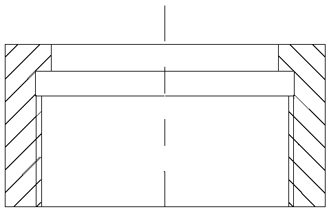
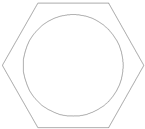
[0031] Specific implementation mode one: refer to Figure 1 to Figure 5 Describe this embodiment in detail. The wire connection clip described in this embodiment includes a clamping sleeve 1, a main cap 2 and a connecting body 3;
[0032] The outer wall of the clamping sleeve 1 near one end is provided with a circle of outer convex edge, and the outer convex edge divides the clamping sleeve 1 into two parts, one part is a hollow cylinder, and the other part is a hollow circular platform. The connecting body 3 has at least one inner wall and the clamping The outer wall of the hollow circular platform of set 1 coincides;
[0033] The main cap 2 is hexagonal, and one end of the main cap 2 is radially inwardly provided with a ring of clamping edge, and the clamping edge of the main cap 2 tightly engages the clamping sleeve 1 through the outer convex edge of the clamping sleeve 1 In the connection body 3 , the outer diameter of the wire is equivalent to the inner diameter of the c...
specific Embodiment approach 2
[0037] Specific implementation mode two: refer to Figure 6 to Figure 7 Describe this embodiment in detail. This embodiment is a further description of the wire connection clamp described in Embodiment 1. In this embodiment, the clamping sleeve 1 is provided with 4 slits along the axial direction, one of which is the main slit, and the rest 3 are auxiliary gaps. The 4 slots are evenly distributed on the clamping sleeve.
[0038] When tightening the main cap 2, since the clamping sleeve 1 has a gap, the clamping sleeve can be screwed forward as far as possible, and the inner diameter of the clamping sleeve 1 gradually decreases during the screwing process, thereby increasing the distance between the clamping sleeve and the The contact area of the wire is reduced to reduce the contact resistance.
specific Embodiment approach 3
[0039] Specific implementation mode three: refer to Figure 8 This embodiment will be specifically described. This embodiment is a further description of the wire connection clamp described in the second embodiment. In this embodiment, the connecting body 3 is a straight line, and one end of the connecting body 3 is provided with a clamping sleeve 1. The other end is a terminal block.
[0040] According to the needs of use, the other end of the connecting body 3 is a connection terminal, which broadens the use range of the wire connection clamp.
PUM
 Abstract
Description
Claims
Application Information
 - R&D
- Intellectual Property
- Life Sciences
- Materials
- Tech Scout
- Unparalleled Data Quality
- Higher Quality Content
- 60% Fewer Hallucinations
Browse by: Latest US Patents, China's latest patents, Technical Efficacy Thesaurus, Application Domain, Technology Topic, Popular Technical Reports.
© 2025 PatSnap. All rights reserved.Legal|Privacy policy|Modern Slavery Act Transparency Statement|Sitemap|About US| Contact US: help@patsnap.com


