Control method and system for vehicle and vehicle

A control method and technology of a control system, which are applied to control devices, vehicle components, and driver input parameters, etc., can solve the problems that the overall performance of the vehicle cannot be exerted, the vehicle cannot automatically adjust the motion state, and the driver's driving intention cannot be guaranteed. , to achieve multi-driving experience and fun, improve ride comfort and active safety, and improve overall performance.

Inactive Publication Date: 2018-07-31
GREAT WALL MOTOR CO LTD
View PDF10 Cites 11 Cited by
  • Summary
  • Abstract
  • Description
  • Claims
  • Application Information

AI Technical Summary

Problems solved by technology

[0004] 1) Disadvantages of interaction between subsystems: At present, the vehicle chassis control system is simply superimposed, and each subsystem operates independently. A complete closed loop cannot be formed between the main control unit and each subsystem. There is no feedback, and the driver's driving intention cannot be guaranteed. ; Where there are functional conflicts between the main control unit and each subsystem, they cannot be well coordinated, resulting in the failure of the overall performance of the vehicle
[0005] 2) Disadvantages of driving mode functions: previous models only had a single mode switch, and did not have the advantages of intelligent chassis control systems in terms of improving ride comfort, handling and active safety. The subsystem executes the defined mode, and the vehicle cannot automatically adjust the motion state according to its own state information

Method used


Image

  • Control method and system for vehicle and vehicle
  • Control method and system for vehicle and vehicle
  • Control method and system for vehicle and vehicle

Examples


Embodiment Construction

[0037] It should be noted that, in the case of no conflict, the embodiments of the present invention and the features in the embodiments can be combined with each other.

[0038] The present invention will be described in detail below with reference to the accompanying drawings and examples.

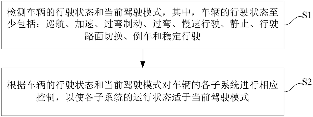
[0039] figure 1 is a flowchart of a vehicle control method according to an embodiment of the present invention.

[0040] Such as figure 1 As shown, the vehicle control method in the embodiment of the present invention includes the following steps: .

[0041] Step S1: Detect the driving state and current driving mode of the vehicle, wherein the driving state of the vehicle at least includes: cruising, acceleration, cornering braking, cornering, slow driving, stationary, driving road switching, reversing and stable driving.

[0042] In one embodiment of the present invention, for example, according to the vehicle's yaw rate signal, lateral acceleration signal, longitudinal acceleration ...


PUM


Abstract

The invention provides a control method and system for a vehicle and a vehicle. The control method for the vehicle comprises the following steps of detecting running states and current driving mode ofthe vehicle, wherein the running states of the vehicle at least comprise a cruising state, an accelerating state, a turning braking state, a turning state, a low speed running state, a static state,a running pavement switching state, a reversing state and a stable running state; and correspondingly controlling each sub system of the vehicle according to the running states and the current drivingmode of the vehicle so that the operation state of each sub system is suitable for the current driving mode. According to the control method for the vehicle, the suitable operation state of each subsystem under the corresponding road condition can be intelligently adjusted according to the state and driving mode of the vehicle so that the comfort and active safety of the vehicle are improved andthe driving experience feeling and driving interest of a driver are also improved.

Description

technical field [0001] The invention relates to the technical field of automobiles, in particular to a vehicle control method, system and vehicle. Background technique [0002] With people's pursuit of automobile performance, there are more and more chassis control systems, and the integration of chassis control systems is also the general trend. For example, the intelligent driving mode control system is an electronically controlled driving assistance system. After changing the driving mode, the vehicle will show different driving performances (such as sports, comfort, economy, etc.). The intelligent driving mode control system can meet the needs of different customers to a greater extent, and can also improve the maneuverability and stability of the vehicle in different driving modes. The intelligent driving mode control system issues commands by manipulating the switch, and the main control unit sends the command to each subsystem through the CAN network after receiving...

Claims


Application Information

Patent Timeline
Patent Type & Authority Applications(China)
IPC IPC(8): B60W30/02B60W50/00
CPCB60W30/025B60W50/0098B60W2510/1005B60W2520/10B60W2520/105B60W2520/125B60W2520/28B60W2540/18B60W2710/10B60W2710/18B60W2710/20
Inventor 孙玉刘自敏牛小锋周申光张凯邦孔凡茂马龙兴郝兴刘天培周铁曾迁贾具宾梁延召
Owner GREAT WALL MOTOR CO LTD
Why Eureka
Try Eureka