Supercharge Your Innovation With Domain-Expert AI Agents!

Adjacent-chamber object conveying mechanism for medical instrument production

A technology of medical equipment and room transmission, which is applied in the direction of transportation and packaging, slideways, etc., can solve the problems of laborious noise, pollution, etc., and achieve the effect of preventing damage

Inactive Publication Date: 2018-07-31
JIANGSHAN XIANJIN ELECTRICAL & MECHANICAL TECH SERVICES CO LTD
View PDF4 Cites 0 Cited by
  • Summary
  • Abstract
  • Description
  • Claims
  • Application Information

AI Technical Summary

Problems solved by technology

[0003] The invention provides an adjacent room transfer mechanism for medical device production that does not need to be called when transferring objects, which solves the problems of labor and noise pollution caused by the need for manual calls for the existing manual transfer of objects

Method used


Image

  • Adjacent-chamber object conveying mechanism for medical instrument production
  • Adjacent-chamber object conveying mechanism for medical instrument production
  • Adjacent-chamber object conveying mechanism for medical instrument production

Examples


Embodiment 1

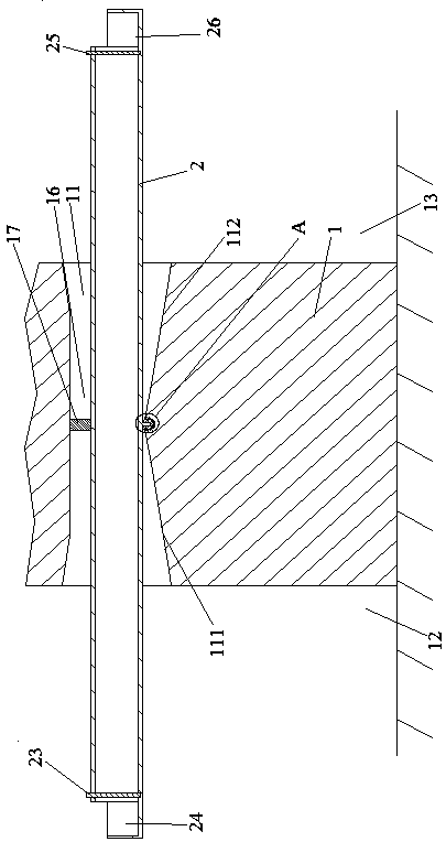
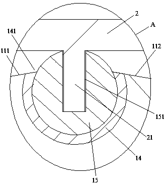
[0018] Embodiment one, see figure 1 with figure 2 , an adjacent chamber transfer mechanism for medical device production, comprising a left chamber 12 and a right chamber 13 separated by a wall 1 . The wall 1 is provided with a communicating hole 11 communicating the left ventricle and the right ventricle. A left inclined section 111 is provided at the left end of the bottom wall of the communication hole, and a right inclined section 112 is provided at the right end. A round steel pipe 14 is poured at the junction of the left inclined section and the right inclined section. The round steel pipe extends horizontally and is perpendicular to the center line of the communication hole. An opening 141 is provided on the upper portion of the peripheral surface of the round steel pipe. The opening extends along the axial direction of the round steel pipe. The round steel pipe is worn on the rotating shaft 15. The upper side of the rotating shaft is exposed in the communication...

Embodiment 2

[0021] Embodiment two, the difference with embodiment one is:

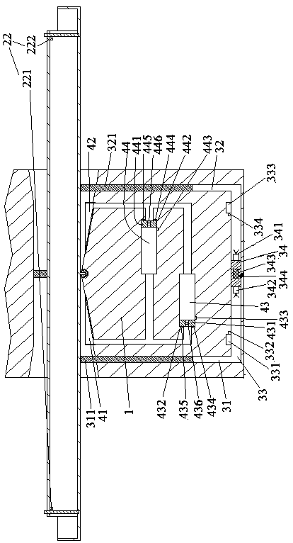
[0022] see image 3, the wall 1 is provided with a left vertical hole 31, a right vertical hole 32 and a sliding hole 33 communicating with the left vertical hole and the right vertical hole. The upper end of the left vertical hole is sealed and slidably pierced with a left push rod 311 supported on the left end of the feeding pipe. The upper end of the right vertical hole is sealed and slidably pierced with a right push rod 321 supported on the right end of the feed pipe. The sliding hole, the left vertical hole and the right vertical rod are filled with hydraulic oil. A piston 34 is sealed and slidably connected in the sliding hole. One end of the piston is connected with a left push propeller 341 which drives the piston to move towards the left vertical hole, and the other end is connected with a right push propeller 342 which drives the piston to move towards the right vertical hole. The piston is provided...


PUM


Abstract

The invention relates to the technical field of medical instruments, and relates to an adjacent-chamber object conveying mechanism for medical instrument production. The mechanism comprises a left chamber and a right chamber which are separated by a wall, and a communicating hole communicates with the left chamber and the right chamber is formed in the wall; a feeding pipe is arranged in the communicating hole in a penetrating mode, and the middle part of the feeding pipe is hinged together to the communicating hole; the feeding pipe is hermetically connected in the communicating hole, the left end of the feeding pipe is provided with a left sealing door for sealing the left end port of the feeding pipe; and the right end of the feeding pipe is provided with a right sealing door for sealing the right end port of the feeding pipe. The invention provides a adjacent-chamber object conveying mechanism for the medical instrument production, and manual calling is not needed when the object is conveyed; and the problems that labor and noise pollutions caused by the manual calling of an existing manual conveying object are solved.

Description

technical field [0001] The invention relates to the technical field of designing medical devices, in particular to an adjacent room transfer mechanism for medical device production. Background technique [0002] In the production process of medical devices, objects need to be transported in two adjacent rooms (clean rooms). The existing method is to open a connecting hole on the wall separating the two rooms, and then pass the material through the connecting hole. The communication hole is blocked by a curtain to prevent the circulation of air in the two rooms. This method requires a manual call to inform the other party to receive or deliver the object when transferring the object, and when the personnel work in the clean room, they wear dust-free clothes, which causes the sound to be blocked, so it is necessary to call loudly to hear, and the loud call is not only It is laborious and also a noise that disturbs others. Contents of the invention [0003] The invention pr...

Claims


Application Information

Patent Timeline
Patent Type & Authority Applications(China)
IPC IPC(8): B65G11/02
CPCB65G11/023
Inventor 余松兰
Owner JIANGSHAN XIANJIN ELECTRICAL & MECHANICAL TECH SERVICES CO LTD
Features
  • R&D
  • Intellectual Property
  • Life Sciences
  • Materials
  • Tech Scout
  • Unparalleled Data Quality
  • Higher Quality Content
  • 60% Fewer Hallucinations
Learn More