A control technology of an environment-friendly biogas generation system

A biogas generation and environmental protection technology, applied in the direction of gas production bioreactors, biological sludge treatment, etc., can solve the problems of uncontrollable feeding and discharging, adjust the amount and time of feeding and discharging materials, and achieve the effect of automatic and convenient addition and remarkable effect

Active Publication Date: 2019-04-23
上海沼鑫环保新能源科技有限公司
View PDF3 Cites 0 Cited by
  • Summary
  • Abstract
  • Description
  • Claims
  • Application Information

AI Technical Summary

Problems solved by technology

[0007] The technical problem to be solved by the present invention is: in the prior art, when manual errors or electronic devices are damaged, it is impossible to adjust the amount and time of the incoming and outgoing materials in real time according to the real-time situation in the biogas digester, which will easily lead to the problem of uncontrollable incoming and outgoing materials. The purpose is to provide a control process for an environmentally friendly biogas generation system that solves the above problems

Method used


Image

  • A control technology of an environment-friendly biogas generation system
  • A control technology of an environment-friendly biogas generation system

Examples


Embodiment 1

[0037] A control process of an environment-friendly biogas generating system, comprising: automatically realizing material feeding and discharging after pretreatment by the biogas generating system.

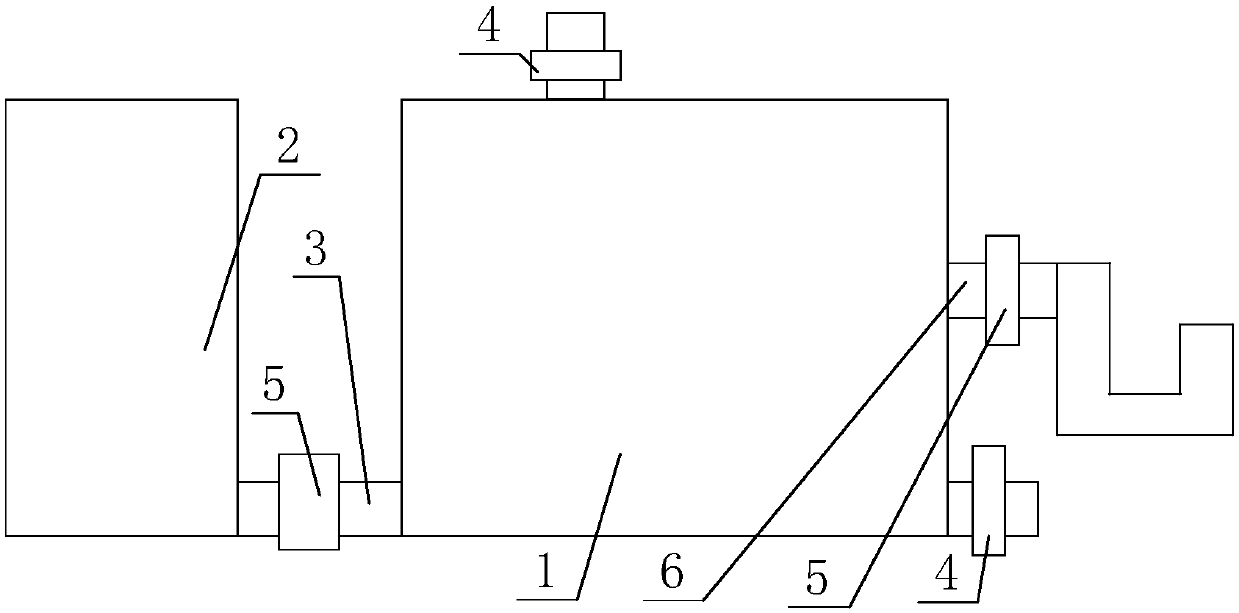
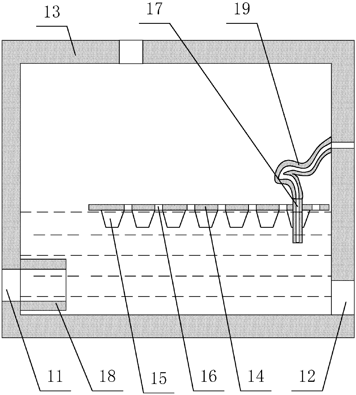
[0038] Among them, such asfigure 1 and figure 2 As shown, the biogas generation system includes a biogas digester 1, a feces storage tank 2 communicated with the biogas digester 1, and the biogas digester 1 includes a biogas digester body 13 having an exhaust port, a feed port 11 and a discharge port 12; The feed port 11 in the biogas digester body 13 is connected with a feed pipe 18 extending into the bottom of the biogas digester body 13;

[0039] The material outlet of the feces storage tank 2 is communicated with the feed port 11 through the connecting pipe 3; an overflow device is installed in the biogas tank body 13, and an overflow port is provided on the top of the biogas tank body 13; the overflow device includes An overflow pipe with one port extending into the biogas...

Embodiment 2

[0054] The difference between this embodiment and Embodiment 1 is that the structure of the overflow device is further optimized in this embodiment, and the specific settings are as follows:

[0055] The overflow device also includes a floating plate 14 placed on the surface of the biogas slurry in the biogas tank body 13, and a float 15 fixed below the floating plate 14; the overflow pipe includes an overflow that runs through the floating plate 14 and extends into the biogas slurry Pipe 17, and a connecting hose 19 with one end in communication with the top port of the overflow inner pipe 17 and the other end in communication with the overflow port; the overflow inner pipe 17 is fixed on the floating plate 14 and is set to extend into the biogas slurry The length of the overflow inner pipe 17 is L, and then L is less than 20cm.

[0056] Through the setting of the structure of the present invention, the scum in the biogas slurry can be effectively isolated and the discharge o...

Embodiment 3

[0058] The difference between this embodiment and Embodiment 2 is that the structures of the floating plate 14, the float 15 and the connecting hose 19 are further optimized in this embodiment, and the specific settings are as follows:

[0059] There are a plurality of floats 15 below the floating plate 14 , and the floats 15 are in a conical structure with a large top and a small bottom, and vent holes 16 are arranged on the floating plate 14 between the floats 15 . The floating plate 14 is made of a hard plastic plate, and the float 15 is made of foamed plastic, and the floating plate 14 floats on the surface of the biogas slurry through the action of the float 15 .

[0060] The connecting hose 19 is a stainless steel metal hose, and the length of the connecting hose 19 is the same as the height of the inner wall of the biogas digester body 13 . The length of the L is 5-10 cm, and the height of the float 15 is at least 1 cm smaller than the L.

[0061] Through the setting o...


PUM

PropertyMeasurementUnit
lengthaaaaaaaaaa

Abstract

The invention discloses a control technology of an environment-friendly biogas generating system, and solves the problems that in the prior art, during a manual fault or damage of an electronic device, the material feeding and discharging amounts and the material feeding and discharging time cannot be adjusted in real time according to the real-time situation in a biogas digester and thus occurrence of feeding and discharging uncontrollability is easily caused. The control technology comprises the step of automatically achieving feeding and discharging after pretreatment through the biogas generating system. The invention further discloses a specific structure of the biogas generating system and specific technological steps of pretreatment. The control technology has the advantages of automatic feeding and discharging and the like.

Description

technical field [0001] The invention belongs to a feces treatment process, and in particular relates to a control process of an environment-friendly biogas generation system. Background technique [0002] Biogas is a combustible gas produced by microbial fermentation of organic matter in an anaerobic environment under certain conditions of temperature, humidity, and pH. [0003] With the development of our country's economy and social progress, the life of urban residents has been further improved, but there are still many problems in the life of rural residents. Due to frequent human activities, a large amount of energy consumption, and a large amount of open-air stacking of straw and livestock and poultry manure, etc., have caused a large amount of carbon dioxide emissions and aggravated the greenhouse effect. [0004] In order to build a well-off society in an all-round way, it is very necessary to build a new socialist countryside. This requires the grand goal of devel...

Claims


Application Information

Patent Timeline
Patent Type & Authority Patents(China)
IPC IPC(8): C02F11/04
CPCC12M21/04
Inventor 李艳芬
Owner 上海沼鑫环保新能源科技有限公司
Why Eureka
Try Eureka