Rapid bridge replacement support base and rapid replacement method for bridge support base
A bridge bearing and bearing technology, which is applied in the field of bridges and construction, can solve the problems of difficult replacement of bearings, and achieve the effects of convenient and easy construction, reduced lifting distance, and reduced impact or damage.
- Summary
- Abstract
- Description
- Claims
- Application Information
AI Technical Summary
Problems solved by technology
Method used
Image

Examples
Embodiment 1
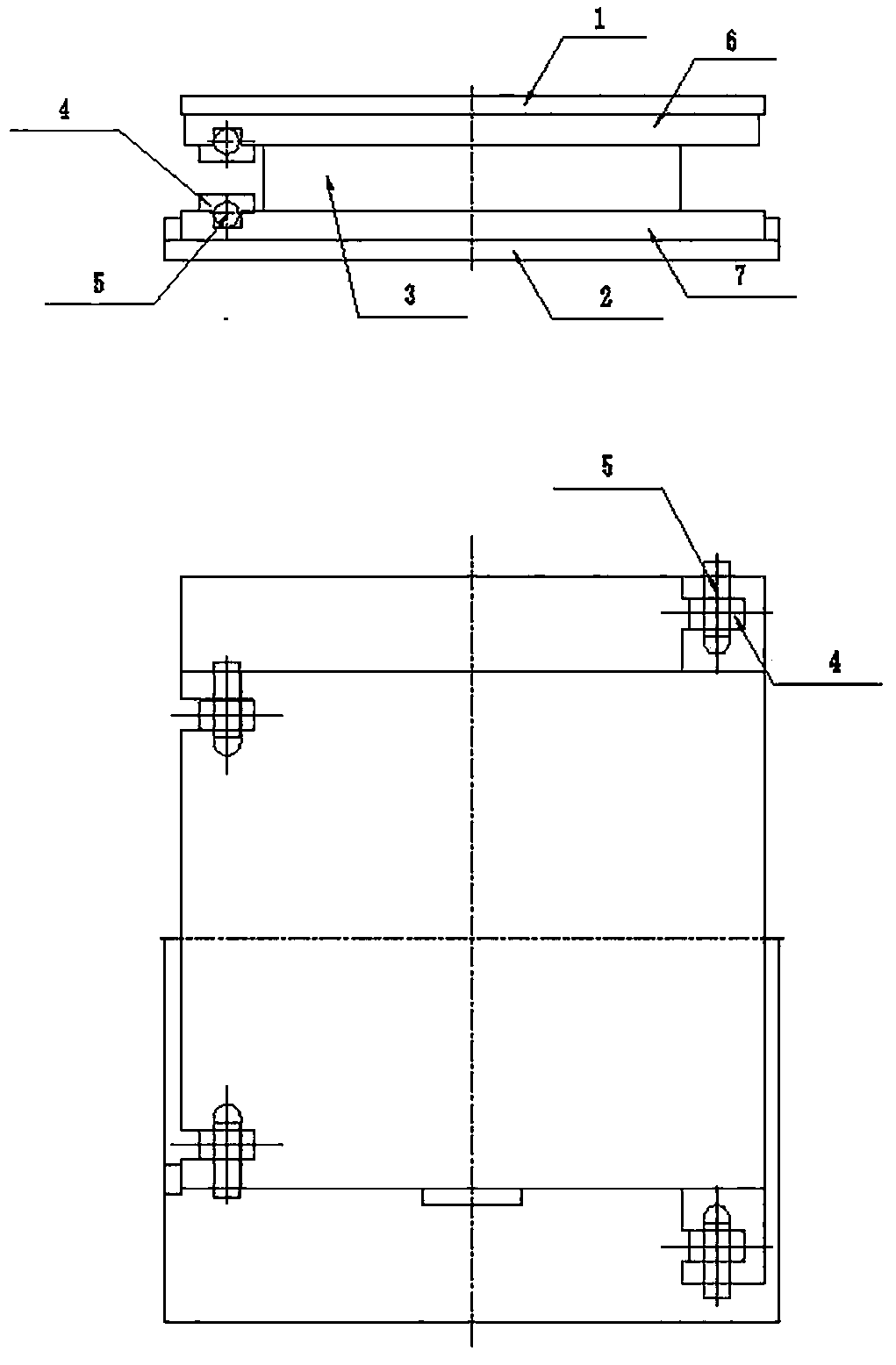
[0037] like figure 1As shown, the bridge quick replacement support of this embodiment includes an upper guide plate 1, a lower guide plate 2, a support body 3, a fixing member 4, a limiting member 5, an upper support plate 6, and a lower support plate 7. The upper support plate 6 and the lower support plate 7 are horizontally provided with mounting holes for fixing parts. The mounting holes for fixing parts in this embodiment adopt U-shaped holes, and the fixing parts 4 are anchored by pre-embedded bridge decks and bridge piers. One end of the anchor bolt of the bridge deck is buried in the concrete of the bridge deck, and the other end is provided with a first limit hole or opening along the horizontal direction. The end of the anchor bolt provided with the first limit hole or opening passes through the upper guide plate 1 Then pass through the U-shaped hole vertically; the position-limiting member described in this embodiment adopts positioning pins, and the upper support pl...
Embodiment 2
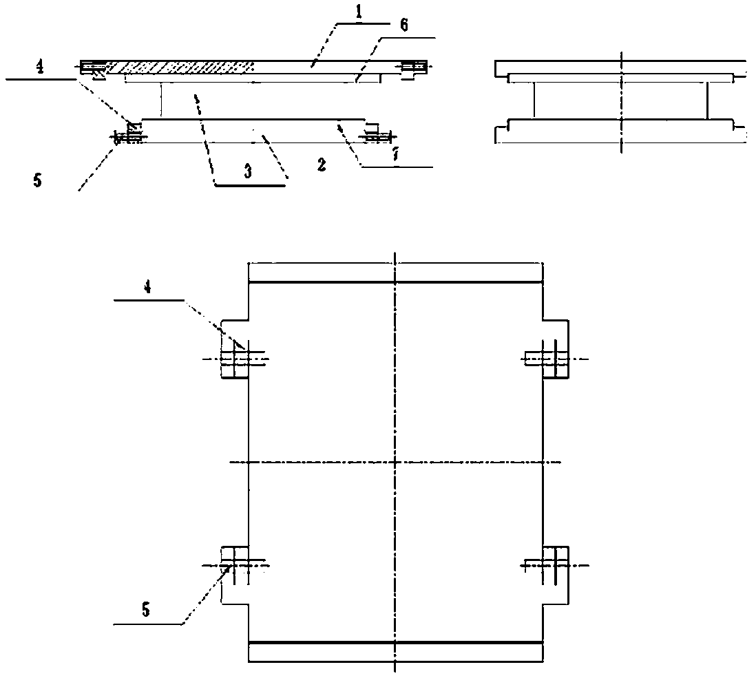
[0042] like figure 2 As shown, the difference between this embodiment and Embodiment 1 is that the mounting holes of the fixing member are provided on the upper guide plate 1 and the lower guide plate 2, and the fixing member 4 adopts an independent positioning block.
[0043] In the same way as in Embodiment 1, when a new support needs to be replaced, it is only necessary to take out the limiter 5 in the horizontal direction, and then take out the fixing member 4 in the horizontal direction, and the original support body 3 can be dragged out in the horizontal direction; install a new For the support, after pushing the new support body 3 in the horizontal direction, put the fixing part 4 in the horizontal direction, and then insert the limiting part 5 in the horizontal direction to fix it. During the entire replacement process, the fixing part 4 and the limiting part 5 do not need to move vertically, so the jacking distance only needs to satisfy a slight gap between the suppo...
Embodiment 3
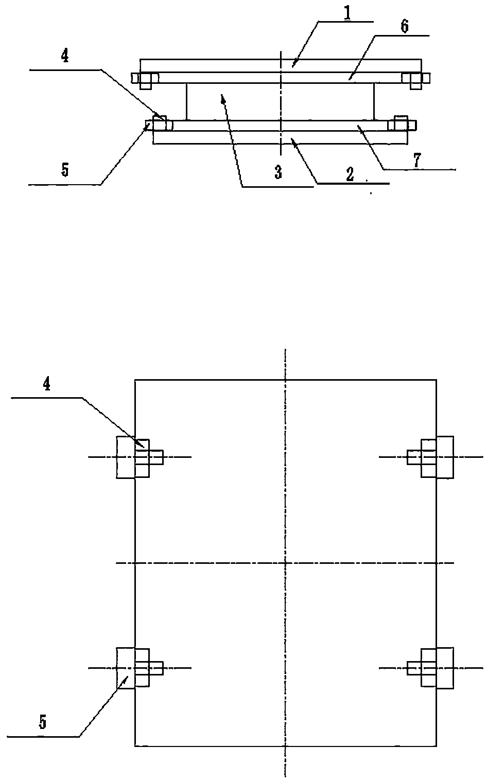
[0044] Embodiment 3: as image 3 As shown, the difference between this embodiment and Embodiment 1 is that the fixing member 4 adopts an independent stopper, and the limiting member 5 adopts a limiting bolt.
[0045] In the same way as in Embodiment 1, when a new support needs to be replaced, it is only necessary to take out the limiter 5 in the horizontal direction, and then take out the fixing member 4 in the horizontal direction, and the original support body 3 can be dragged out in the horizontal direction; install a new For the support, after pushing the new support body 3 in the horizontal direction, put the fixing part 4 in the horizontal direction, and then insert the limiting part 5 in the horizontal direction to fix it. During the entire replacement process, the fixing part 4 and the limiting part 5 do not need to move vertically, so the jacking distance only needs to satisfy a slight gap between the support, the bridge deck, and the bridge pier, and avoid close cont...
PUM
 Abstract
Description
Claims
Application Information
 - R&D
- Intellectual Property
- Life Sciences
- Materials
- Tech Scout
- Unparalleled Data Quality
- Higher Quality Content
- 60% Fewer Hallucinations
Browse by: Latest US Patents, China's latest patents, Technical Efficacy Thesaurus, Application Domain, Technology Topic, Popular Technical Reports.
© 2025 PatSnap. All rights reserved.Legal|Privacy policy|Modern Slavery Act Transparency Statement|Sitemap|About US| Contact US: help@patsnap.com