The general assembly structure of the coiled tube body of the coiled tube heat exchanger and its winding assembly method

A technology of coiled-tube heat exchangers and heat exchange tubes, applied in indirect heat exchangers, heat exchanger types, heat exchanger shells, etc. Leakage and other problems, to achieve the effect of preventing fluid vibration and collision wear, improving reliability and safety, and enhancing connection strength

Active Publication Date: 2019-09-10
LANZHOU LS GRP +1
View PDF7 Cites 0 Cited by
  • Summary
  • Abstract
  • Description
  • Claims
  • Application Information

AI Technical Summary

Problems solved by technology

For example, in the steam generator of a high-temperature gas-cooled reactor, due to the high flow rate of the fluid in the tube, in order to reduce the vibration caused by the fluid in the tube, the spiral tube needs a support with relatively high rigidity to fix it. In addition, the spiral tube can only be assembled with the support after it is formed. This structure has high requirements on the processing accuracy of the support, and the assembly is very difficult; in some chemical equipment, the support of the coiled tube body is a gasket with a toothed structure, and the spiral tube is wound in layers. It is made on the toothed gasket, and the toothed gasket of the adjacent layer is welded and fixed. Although this structure simplifies the assembly of the spiral tube, the toothed gasket can only be processed with a thin plate, which does not have sufficient strength and rigidity, so that the entire The weight of the spiral tube and the fluid in the tube is supported by toothed pads, and the reliability is very low; in addition, the tube head of the spiral tube is welded through the tube plate around the two ends of the tube body, and there is a straight tube section between the tube plate and the spiral tube. The straight pipe sections of all spiral pipes are collected on one side of the tube sheet, and the straight pipe sections cannot be fixed, and the two ends of the winding pipe body are just the inlet and outlet positions of the fluid outside the pipe, and there are flow caused by the fluid outside the pipe and the high-speed fluid inside the pipe. Vibration, long-term vibration and wear of the heat exchange tube wall in the confluence area of ​​the straight tube section, can easily cause fluid leakage in the tube, and there are certain safety hazards

Method used


Image

  • The general assembly structure of the coiled tube body of the coiled tube heat exchanger and its winding assembly method
  • The general assembly structure of the coiled tube body of the coiled tube heat exchanger and its winding assembly method
  • The general assembly structure of the coiled tube body of the coiled tube heat exchanger and its winding assembly method

Examples


Embodiment Construction

[0039] The present invention will be described in further detail below in conjunction with the accompanying drawings.

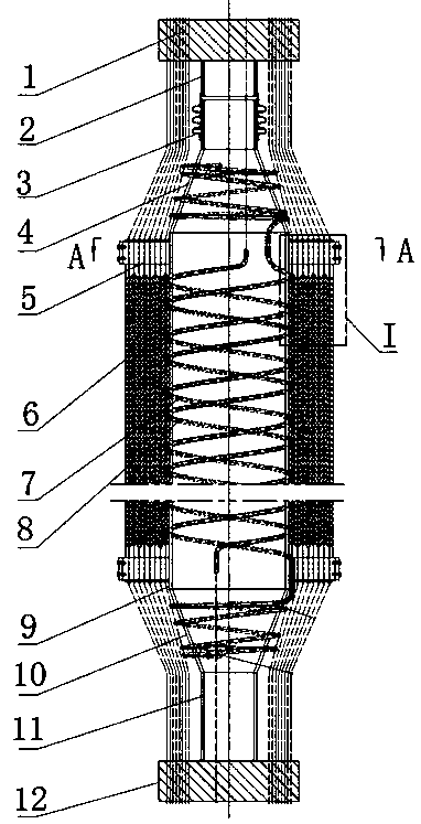
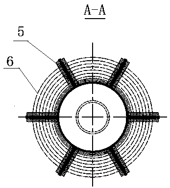
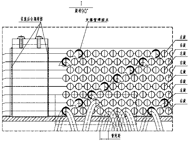
[0040] Such as Figure 1 to Figure 9 The overall assembly structure of a coiled tube heat exchanger is shown, which includes an upper connecting tube 2, an upper cone body 4, a central cylinder body 9, and a lower cone body 10 welded together from top to bottom. And the lower connecting pipe 11, the top of the upper connecting pipe 2 is provided with an upper tube plate 1, the bottom of the lower connecting pipe 11 is provided with a lower tube plate 12, and the outer wall of the central cylinder 9 is surrounded by several layers of spiral heat exchange tubes. 7, the rotation direction of the adjacent two layers of heat exchange tubes 7 is opposite. The middle part is provided with the positioning groove 13 that runs through up and down along the vertical direction, and the two ends of several layers of support bars 6 are stacked successively and then instal...


PUM


Abstract

The invention discloses a winding tube body assembly structure of a winding tube type heat exchanger and a winding and assembling method thereof. The winding tube body comprises a cylindrical body welded as a whole, and the outer wall of the central cylindrical body is surrounded by several layers of spiral heat exchange tubes. , the rotation directions of the two adjacent layers of heat exchange tubes are opposite, and several centripetal positioning plates are symmetrically distributed at both ends of the outer wall of the central cylinder. There are semi-circular positioning holes, and the heat exchange tubes are layered and clamped in the semi-circular positioning holes; one side of each layer of heat exchange tubes is provided with a support tube that is also clamped in the semi-circular positioning holes. The contact surface with the support bar is welded and fixed. In the present invention, the support bars are evenly fixed on the outer wall of the central cylinder through the centripetal positioning plate, so that the weight of each layer of heat exchange tubes and support tubes can be evenly distributed on the centripetal positioning plate, and the difference between the support tubes and the heat exchange tubes is reduced. The load of the support bar improves the reliability and safety of the winding body.

Description

technical field [0001] The invention relates to the technical field of heat exchange equipment, in particular to a tube-wound body assembly structure of a tube-wound heat exchanger and a winding assembly method thereof. Background technique [0002] The coiled tube heat exchanger has compact structure, high heat transfer efficiency and strong thermal compensation ability. Its core component is a coiled tube body formed by alternate winding of multi-layer spiral tubes. In order to prevent the shape of the spiral tube from changing, it must be fixed by supports Spiral tube to prevent deformation of the spiral tube. According to different application occasions of the existing coiled tube heat exchanger, the structure of the supporting member is different, and the way of fixing the spiral tube of the coiled tube body and the supporting member is also quite different, causing many problems. For example, in the steam generator of a high-temperature gas-cooled reactor, due to the ...

Claims


Application Information

Patent Timeline
Patent Type & Authority Patents(China)
IPC IPC(8): F28D7/02F28F9/013F28F9/26B21D11/06B21D11/22B23P15/26
Inventor 叶海董亚军李建仓高亚萍雒旭亮何海涛盛培真王金霞张志敏
Owner LANZHOU LS GRP
Why Eureka
Try Eureka