Device and method for testing anti-scouring capability of soil body

A kind of ability and soil technology, which is applied in the field of devices for testing soil erosion resistance, can solve the problem of no experimental device for testing soil erosion resistance, and achieve the effect of convenient use and simple structure

Active Publication Date: 2018-07-31
CHINA THREE GORGES UNIV
View PDF6 Cites 10 Cited by
  • Summary
  • Abstract
  • Description
  • Claims
  • Application Information

AI Technical Summary

Problems solved by technology

[0003] The technical problem to be solved by the present invention is to provide a device and method for testing soil erosion resistance, which can solve the problem that there is no experimental device for testing soil erosion resistance. The structure is simple, easy to use, and automatically collects data from electronic balances. , the scouring force can be calculated according to the water flow velocity, the time relationship between the scouring force and the particle loss can be established, and the anti-scouring ability of different soil samples can be tested

Method used


Image

  • Device and method for testing anti-scouring capability of soil body
  • Device and method for testing anti-scouring capability of soil body

Examples


Embodiment 1

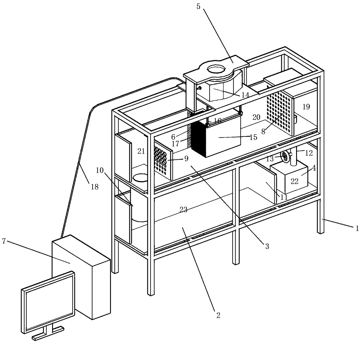
[0033] Such as figure 1 As shown, a device for testing the erosion resistance of the soil, including a load-bearing frame 1,

[0034] The load-bearing frame 1 is provided with an upper water tank 3 and a lower water tank 2, and the inner space of the upper water tank 3 is divided into a water flow entry section 19, a water flow stabilization section 20 and a water flow discharge section by a vertical water inlet mesh plate 8 and a drainage mesh plate 9 21 three parts, the hole diameter on the water inlet sieve plate 8 gradually decreases from top to bottom, so that the water flow for controlling the washing of the sample is stable; the hole diameter on the drainage sieve plate 9 gradually decreases from top to bottom, so that Control the steady flow of water between the two sieve plates.

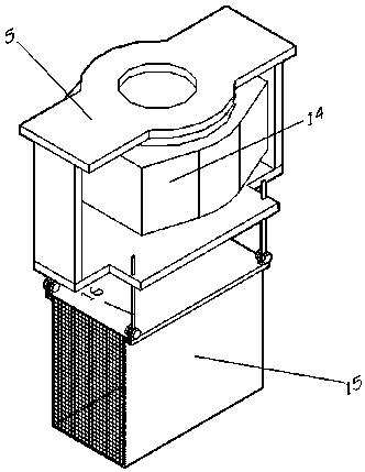
[0035] An electronic balance 14 is installed above the load-bearing frame 1, and the sample frame 5 is composed of a force transmission platform, a dowel bar 16 and a sample box 15. The sam...

Embodiment 2

[0043] A method for testing soil erosion resistance by using the above-mentioned device, the method includes the following steps:

[0044] Step 1: close the valve 13;

[0045] Step 2: Add water of 3 / 4 of the volume of the lower tank into the lower tank 2;

[0046] Step 3: Open the valve 13 and start the variable frequency water pump 4 at the same time;

[0047] Step 4: Continue to add water to the sink 2;

[0048] Step 5: The frequency conversion water pump 4 sends the water in the lower water tank 2 to the upper water tank 3 through the upper water pipe 12, until the upper water tank 3 and the lower water tank 2 form a circulation system through the frequency conversion water pump 4 and the connecting water channels at both ends, and then stop adding water;

[0049] Step 6: Put the prepared soil sample into the sample box 15, and then cover with a detachable plexiglass cover;

[0050] Step 7: Turn on the electronic balance 14, and reset the reading of the electronic balanc...


PUM

PropertyMeasurementUnit
thicknessaaaaaaaaaa

Abstract

The invention discloses a device for testing the anti-scouring capability of a soil body. The device comprises a bearing frame, wherein the bearing frame is provided with an upper water tank and a lower water tank; an inner space of the upper water tank is divided by a vertical water inflow sieve tray and a water drainage sieve tray into a water flow inflow section, a water flow stabilizing section and a water flow draining section; a sample holder is installed at the upper part of the bearing frame; a force transferring platform with an electronic scale in the sample holder is connected witha sample box through a plurality of force transferring rods; the sample box extends into the water flow stabilizing section; the end face, vertical to the water flow, of the sample box is a metal meshsurface; and a velocimeter is arranged in the water flow stabilizing section. The device and method, provided by the invention, for testing the anti-scouring capability of the soil body solves the problem that no experimental facility is provided for testing the anti-scouring capability of the soil body, the device is simple in structure and convenient to use, the data of the electronic scale areautomatically acquired, the scouring force is calculated according to the water velocity, the time relation between the scouring force and the particle loss amount is established, and the anti-scouring capability of different soil samples is tested.

Description

technical field [0001] The invention relates to the field of rock and soil experiments, in particular to a device and a method for testing soil erosion resistance. Background technique [0002] With the establishment of large reservoirs in my country, a large number of new reservoir banks have been formed, and the anti-scouring capacity of reservoir bank slopes is mainly affected by internal and external factors. The internal factors are mainly the composition of the soil and the physical and mechanical indicators such as the moisture content, dry density, and cohesion c of the soil. The external factors are mainly the flow velocity, water temperature and flow state of the reservoir water. At present, some scholars have tried to carry out qualitative tank experiments and field experiments, but the experimental variables are difficult to control and the measurement accuracy is difficult to guarantee. Contents of the invention [0003] The technical problem to be solved by...

Claims


Application Information

Patent Timeline
Patent Type & Authority Applications(China)
IPC IPC(8): G01N3/56
CPCG01N3/565G01N3/567G01N2203/0242
Inventor 陈勇邓合玉苏剑隆海鹏
Owner CHINA THREE GORGES UNIV
Why Eureka
Try Eureka