Thermally highly conductive coating on base structure accommodating component

A high thermal conductivity, substrate technology, used in circuit thermal components, printed circuit components, semiconductor/solid-state device components, etc.

Active Publication Date: 2018-07-31
AT & S CHINA
View PDF5 Cites 16 Cited by
  • Summary
  • Abstract
  • Description
  • Claims
  • Application Information

AI Technical Summary

Problems solved by technology

This is particularly difficult in practice, as a considerable amount of heat is generated during operation when the part is embedded

Method used


Image

  • Thermally highly conductive coating on base structure accommodating component
  • Thermally highly conductive coating on base structure accommodating component
  • Thermally highly conductive coating on base structure accommodating component

Examples


Embodiment Construction

[0053] Before referring to the drawings, exemplary embodiments will be described in further detail and some basic considerations upon which exemplary embodiments of the invention have been formed will be outlined.

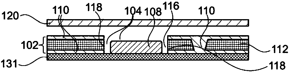
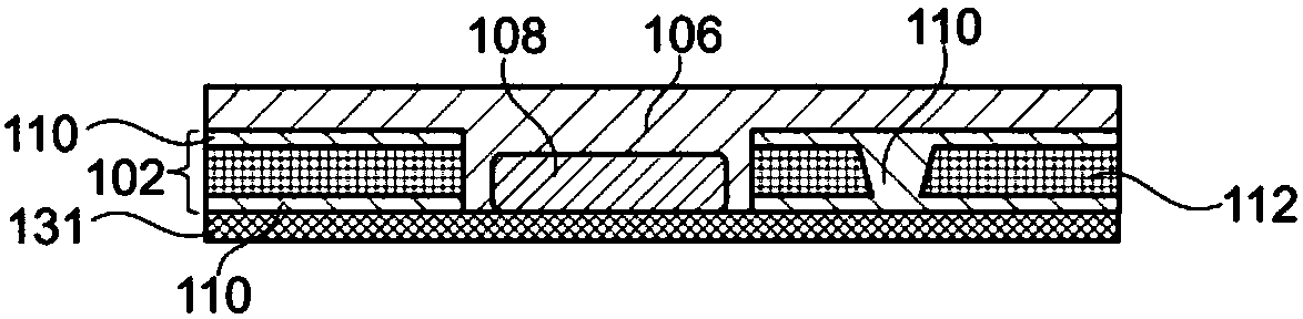
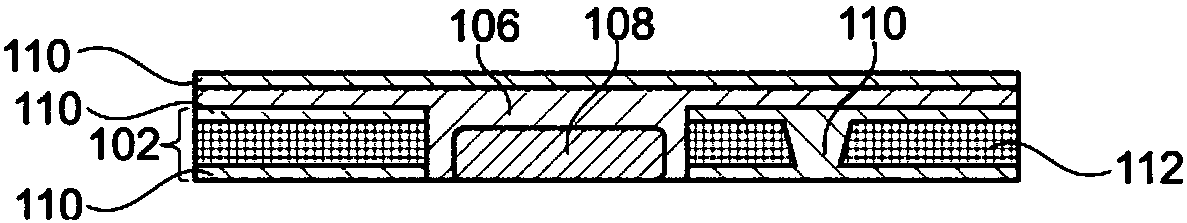
[0054] According to an exemplary embodiment of the invention, heat can be dissipated directly in the case of embedding the component in the component carrier. One gist according to an exemplary embodiment is to allow heat to dissipate from the area of ​​the component carrier where the component is placed. By taking this measure, it is possible to reduce the thermal cycle range, or lower the operating temperature in the area around the embedded component and on / on the component itself which is subject to high heat dissipation. According to an exemplary embodiment, the component carrier design is configured to allow for improved heat flow and dissipation from the area in which the component is embedded. Several materials can be advantageously implemented for this pu...


PUM


Abstract

A component carrier (100) comprises a base structure (102) with a recess (104), a thermally highly conductive coating (106) covering at least a part of a surface of the base structure (102) and a component (108) in the recess (104).

Description

technical field [0001] The invention relates to a method for producing a component carrier and to a component carrier. Background technique [0002] In the case of the development of product functions of component carriers equipped with one or more electronic components, the increasing miniaturization of such components, and the rise in the number of components to be mounted on component carriers such as printed circuit boards, more and more More powerful array-like components or packages with several components with multiple contacts or connections with ever-decreasing spacing between these contacts are increasingly being used. Removing the heat generated during operation by such components and the component carriers themselves is becoming an increasing problem. At the same time, the component carrier should be mechanically robust and electrically reliable in order to be able to operate even under harsh conditions. [0003] Furthermore, it is a problem to embed components...

Claims


Application Information

Patent Timeline
Patent Type & Authority Applications(China)
IPC IPC(8): H05K1/02H05K1/18H05K3/30H01L23/373H01L23/42
CPCH01L23/3735H01L23/42H05K1/0203H05K1/185H05K3/30H05K2201/06H01L21/56H01L23/3121H01L23/3737H01L23/5389H01L24/19H01L24/20H01L2224/04105H01L2224/18H01L2224/2518H01L2224/92144H01L2924/0001H01L23/373H05K1/0201H05K7/20
Inventor 米凯尔·图奥米宁安妮·泰阿尔坦·巴弗蒂里
Owner AT & S CHINA
Why Eureka
Try Eureka