Heated catheter used in cryotherapy

a cryotherapy and catheter technology, applied in the field of cryosurgery, can solve the problems of cell death, cell organelle and protein damage, maximum cell death, etc., and achieve the effect of shorter cryoburn exposure time, higher nozzle pressure, and higher nozzle pressur

Inactive Publication Date: 2007-08-14
CSA MEDICAL
View PDF26 Cites 96 Cited by
  • Summary
  • Abstract
  • Description
  • Claims
  • Application Information

AI Technical Summary

Benefits of technology

[0016]A completely automated system with sensors and a microprocessor are employed for performing cryosurgery. It is an important preferred feature of the present invention that the spray be conducted in such a manner as to allow constant visualization by the physician of the tissue treatment as it occurs. If the temperature of the lens at the distal end of the endoscope drops precipitously at the start of the liquid nitrogen spray, the moist air of the esophageal environment or of the air of the catheter which has been blown out ahead of the nitrogen flow will condense on the lens, thereby obscuring the physician's view of the operative site. This can be substantially avoided by means of the suction pump which will immediately suck out the moist air which is present prior to the arrival of the liquid nitrogen spray or cold nitrogen gas. Because of this pumping out of the moist air as the spray commences and the replacement with extremely dry nitrogen gas, substantial amounts of moisture will not form on the lens during the procedure, allowing an excellent view of the operative site by the physician during the procedure.
[0043]It is clear from experiments performed that a bleeder valve is not absolutely essential to this invention since low pressure cryoablation can be carried out through low head pressure in the storage tank or through selection of the proper inner diameter of the catheter. Based on experiments carried out with the bleeder valve embodiment a shorter time period is required for cryoburn.

Problems solved by technology

Mazur demonstrated that rapid freezing and slow warming lead to maximum cell death.
If cell hypothermia is of sufficient duration, cell organelle and protein damage will occur leading to cell death through physical breakdown of the cell membrane or through induction of genetically controlled apoptosis.
Consequent to this is vasoconstriction and microthrombi formation in the venules and capillaries resulting in vascular stasis.

Method used


Image

  • Heated catheter used in cryotherapy
  • Heated catheter used in cryotherapy
  • Heated catheter used in cryotherapy

Examples


Embodiment Construction

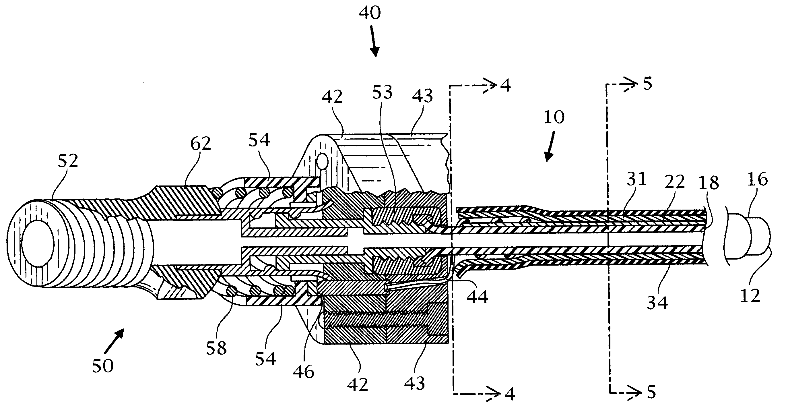
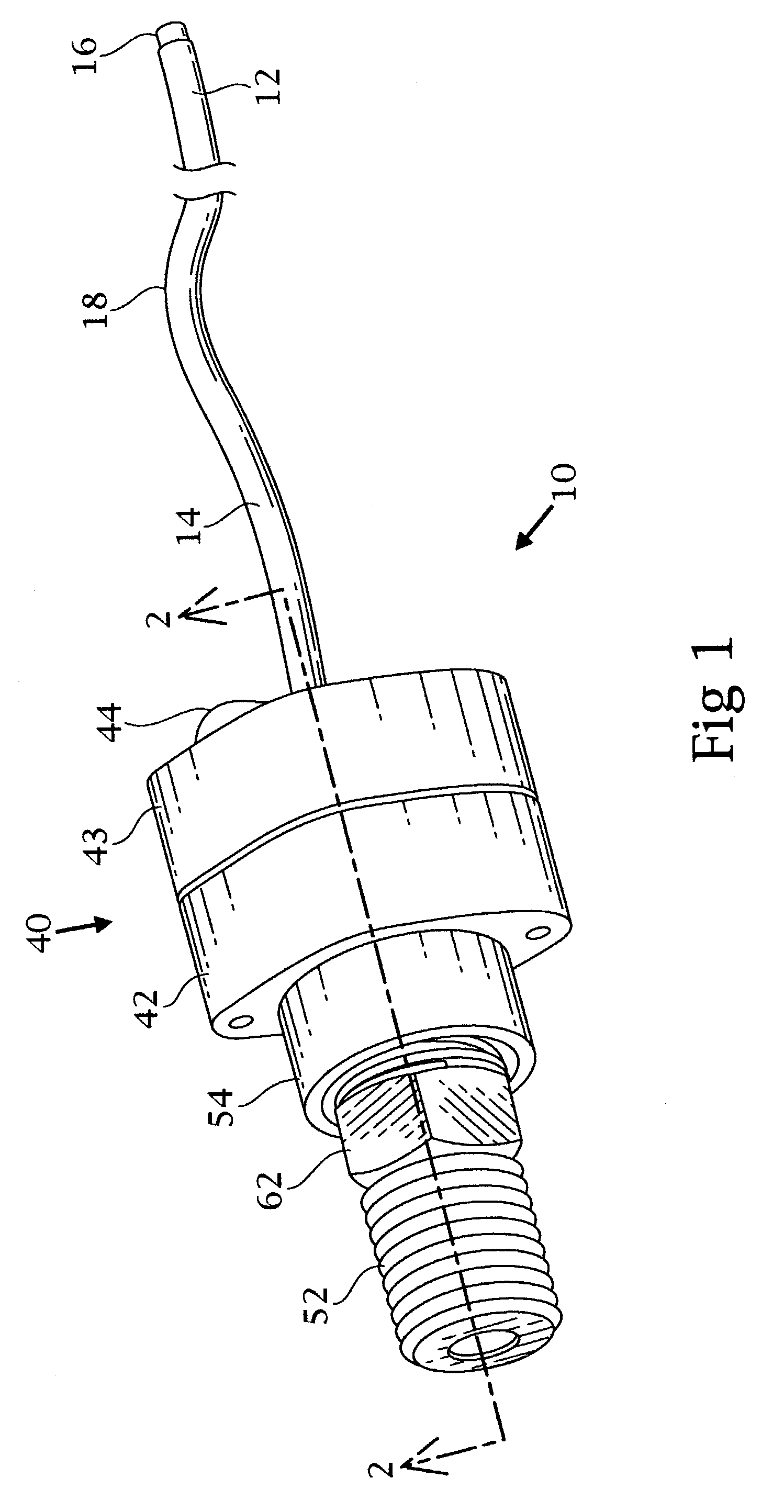
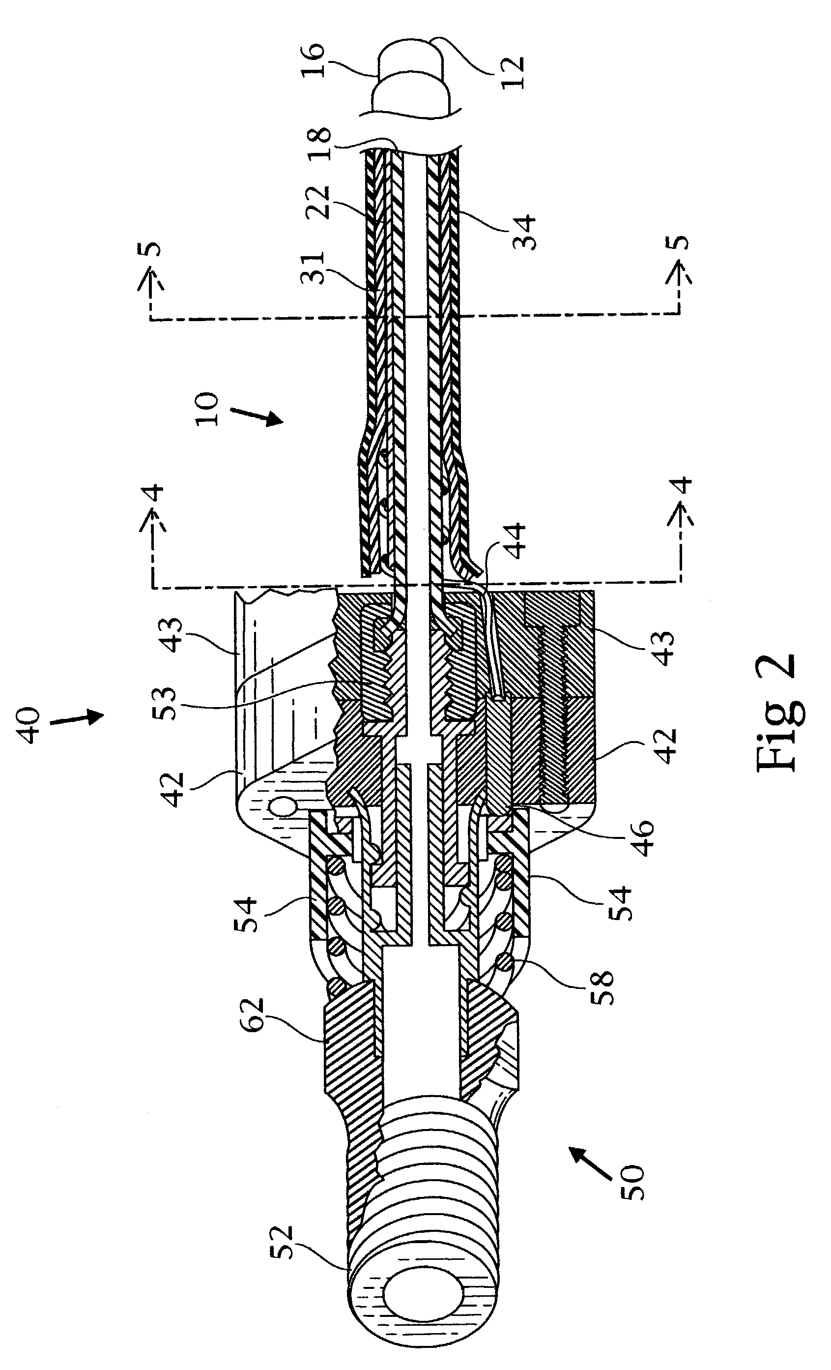
[0078]With reference to FIGS. 1 and 2, a heated catheter assembly 10 has a catheter 18 with a distal end 12 and a proximal end 14. As part of the catheter assembly 10 there are a hub 40 having a top portion 42 and a base 43. The top portion 42 of the hub 40 has a gas and electric connector subassembly 50 for attaching the gas line and two contact points for making electric contact with the luer lock and threaded gas nipple 52 (described more fully in FIGS. 19-27).

[0079]Referring to FIGS. 3-6, the order for constructing the heated catheter is shown in cross-section. Catheter 18 is shown in FIG. 3. FIG. 4 describes the catheter 18, with internal copper wire 28, the external copper wire 20 outside of the catheter and copper foil 22. Copper wire 20 being attached to copper foil 22. Wire 28 runs the length of the internal portion of the catheter 18 and exits at the distal end where it is held in place by a hypodermic tube or stainless sleeve 38 (see FIG. 9). The stainless sleeve 38 press...


PUM


Abstract

Disclosed is a cryosurgical catheter which is heated in order to prevent its freezing within the lumen of an endoscope. The catheter is to be used with an endoscope to perform cryoablation on an internal tissue; e.g., the esophagus. Electric conductivity to produce heat employs an electrical conductive coating on the catheter. Also, disclosed is a fitting for use with a catheter comprising both a connection for receiving gas and an electrical connection.

Description

RELATED APPLICATIONS[0001]This application is a continuation-in-part of Ser. No. 10 / 106,985 filed Mar. 26, 2002, now U.S. Pat. No. 7,025,762; which is a continuation-in-part of Ser. No. 09 / 477,839 filed Jan. 5, 2000 now U.S. Pat. No. 6,383,181 which in turn is a continuation-in-part of Ser. No. 09 / 050,150 filed Mar. 30, 1998 now U.S. Pat. No. 6,027,499 which claims benefit of Provisional Application Ser. No. 60 / 047,484 filed May 23, 1997, the disclosures of which are herein incorporated by reference.FIELD OF THE INVENTION[0002]The invention finds applicability in the field of cryosurgery where a catheter is used to convey a cryogas to ablate tissue.BACKGROUND OF THE INVENTION[0003]In a companion application filed by the inventors, there is claimed a method for ablation of tissue in the esophagus using a cryogenic gas. In a specific therapeutic application, Barrett's esophagus is treated, although other intestinal lesions may also be treated. While the therapeutic treatment is effect...

Claims


Application Information

Patent Timeline
Patent Type & Authority Patents(United States)
IPC IPC(8): A61B18/02
CPCA61B18/02A61B18/08A61B2018/00101A61B2018/0212
Inventor JOHNSTON, MARK H.CARTLEDGE, JENNIFER B.
Owner CSA MEDICAL
Why Eureka
Try Eureka