Mitral or tricuspid heart valve prosthesis

A technology for heart valves and tricuspid valves, applied in the fields of heart valves, prostheses, medical science, etc., can solve problems such as migration blocking the ventricular ejection path, and no implantation site

Active Publication Date: 2018-07-31
ヴァルミーホールディング
View PDF8 Cites 2 Cited by
  • Summary
  • Abstract
  • Description
  • Claims
  • Application Information

AI Technical Summary

Problems solved by technology

[0006] Existing prostheses of this type are not entirely satisfactory, especially with the risk of migration and thus blocking the ventricular ejection path, with a placement that is not always very easy to work, not with a perfectly adapted implantation site and involves the placement of a passage orifice leading to the implantation site with a relatively large diameter, and thus it is relatively traumatic

Method used


Image

  • Mitral or tricuspid heart valve prosthesis
  • Mitral or tricuspid heart valve prosthesis
  • Mitral or tricuspid heart valve prosthesis

Examples


Embodiment Construction

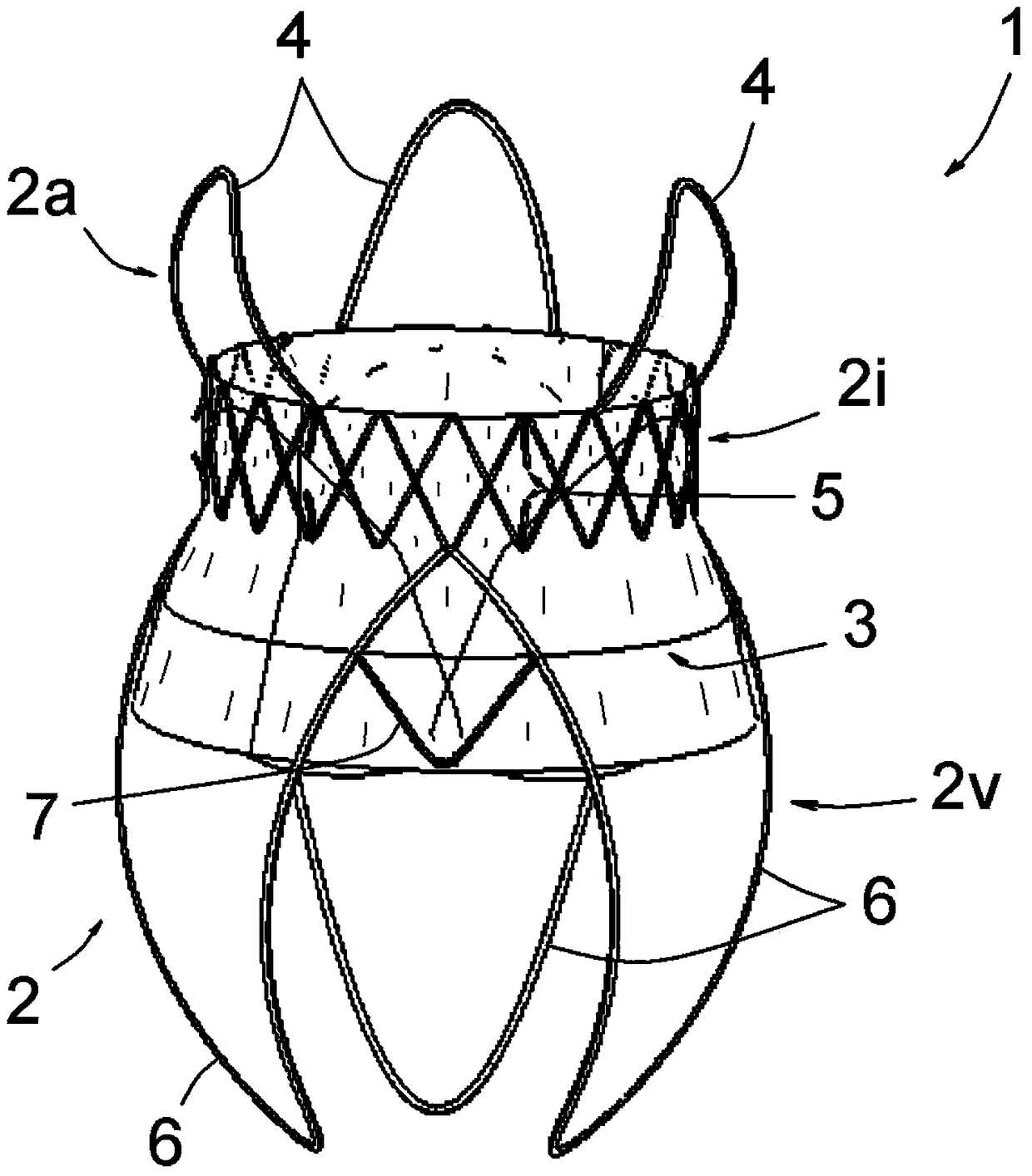
[0036] The figures show a prosthetic mitral or tricuspid heart valve 1 comprising an expandable tubular frame 2 and a prosthetic valve 3 mounted on this frame.

[0037] The frame 2 has a structure made of elastically deformable filaments allowing it to assume the expanded form shown in the figures and the contracted form in which it can be contained in a catheter (not shown) for insertion into the heart. It may in particular be made of shape memory alloys, in particular nickel and titanium known as nitinol, using known techniques.

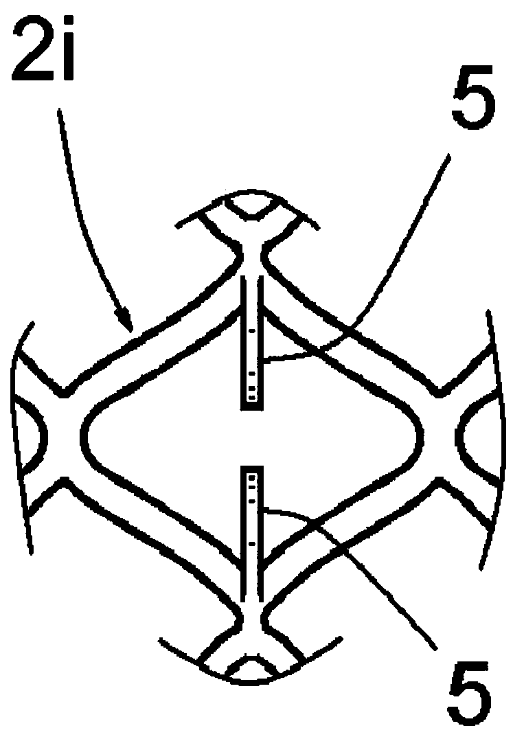
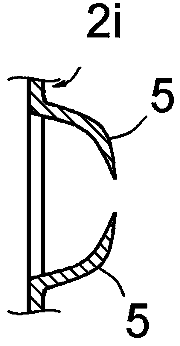
[0038] The frame 2 comprises: an atrial portion 2a, ie intended to be placed at the atrium of the heart; a ventricular portion 2v, ie intended to be placed at the ventricle of the heart; and an intermediate annulus portion 2i, which is located between these atrium 2a and ventricle 2v portions , intended to be placed at the native valve annulus.

[0039] The atrial portion 2a is formed by three wire extensions 4 regularly distributed over its circu...


PUM


Abstract

The invention relates to a mitral or tricuspid heart valve prosthesis (1) which comprises an expansible tubular frame (2) and a prosthetic valve (3) mounted on said frame. The frame comprises an atrial portion (2a), a ventricular portion (2v) and an annular portion (2i) located between said atrial and ventricular portions, wherein: the atrial portion (2a) is made up of three or four metal-wire extensions (4), regularly distributed on the circumference of said atrial portion (2a) and projecting from said annular portion (2i), each extension (4) being made up of a single upside-down U-shaped orV-shaped wire and the various extensions (4) being substantially part of an imaginary truncated sphere placed above said annular portion (2i); said annular portion (2i) is made up of diamond meshes which comprise anchoring points (5); and said ventricular portion (2v) is made up of three or four extensions (6) equivalent to the extensions (4), substantially contained inside an imaginary ovoid shape placed under said annular portion (2i).

Description

technical field [0001] The invention relates to a mitral or tricuspid heart valve prosthesis. Background technique [0002] A well-known pathology of heart valves that primarily affects elderly patients is dilation of the valve annulus, which leads to poor coaptation of the valve and thus to loss of seal and effectiveness of the valve. [0003] It is known to treat this pathology by annuloplasty, ie by placing all or part of a prosthetic annulus in order to recalibrate the native annulus. This technique has certain disadvantages, especially in elderly patients. [0004] It is also known to implant over a native valve a prosthesis comprising an expandable tubular frame and a prosthetic valve mounted on this frame. The tubular frame (commonly referred to as a "stent") has a lattice structure and includes: an atrial portion, i.e., intended to be placed at the atria of the heart; a ventricular portion, i.e., intended to be placed at the ventricles of the heart; and an annulus ...

Claims


Application Information

Patent Timeline
Patent Type & Authority Applications(China)
IPC IPC(8): A61F2/24
CPCA61F2/2412A61F2220/0016A61F2230/0054A61F2230/0071A61F2230/0076A61F2/2418A61F2/2487
Inventor 托马斯·莫迪恩
Owner ヴァルミーホールディング
Why Eureka
Try Eureka