Charging detection circuit, charging box, communication device of earphone, and earphone

A charging detection and detection circuit technology, applied in the electronic field, can solve the problems of reduced charging efficiency, small charging current, and weak voltage, so as to avoid changes in usage habits and improve user experience

Active Publication Date: 2018-07-31
SHENZHEN WEITONGBO TECH CO LTD
View PDF4 Cites 7 Cited by
  • Summary
  • Abstract
  • Description
  • Claims
  • Application Information

AI Technical Summary

Problems solved by technology

It can be found that in the prior art, the charging current is calculated after converting the current into a voltage through the sampling resistor 110, which will cause a fixed loss on the resistor and reduce the charging efficiency; in addition, because the sampling resistor 110 converts the current into a voltage, resulting in When charging and entering the constant voltage mode, the charging current is getting smaller and smaller, the voltage converted by the resistor is getting weaker and weaker, and the dynamic range is smaller, which makes it difficult for the processor to distinguish such signals

Method used


Image

  • Charging detection circuit, charging box, communication device of earphone, and earphone
  • Charging detection circuit, charging box, communication device of earphone, and earphone
  • Charging detection circuit, charging box, communication device of earphone, and earphone

Examples


Embodiment Construction

[0042] The technical solutions of the embodiments of the present application will be described below in conjunction with the accompanying drawings.

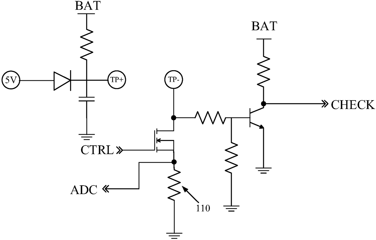
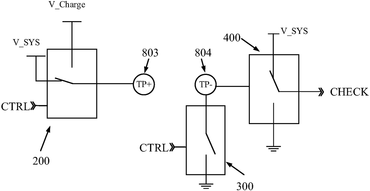
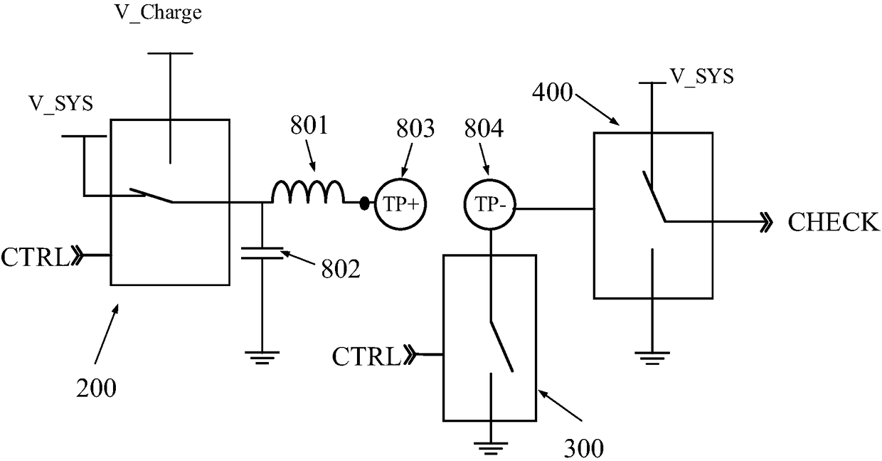
[0043] An embodiment of the present application provides a charging detection circuit. It should be understood that the charging detection circuit of the embodiment of the present application may be applicable to any charging device; for example, a charging box, a mobile power supply, and the like. The charging detection circuit in the embodiment of the present application can also be applied to any first device that needs to be charged; for example, the first device used in conjunction with the above-mentioned charging device; another example is smart wearable devices such as earphones and bracelets; and For example, mobile phones, tablets, laptops, computers, MP3 and MP4, etc. For ease of understanding, the embodiment of the present invention assumes that the charging device is a charging box and the first device is an earphon...


PUM


Abstract

Provided are a charging detection circuit, a charging box, a communication device of an earphone, and an earphone. The charging detection circuit comprises a first contact, a second contact, a switching circuit, a charging circuit, a detection circuit, and a first communication circuit. The switching circuit is connected with the first contact. The charging circuit is connected with the detectioncircuit through the second contact. The first communication circuit is connected with the first contact and/or the second contact. Supply voltage of the first contact is system voltage. When the firstcontact and the second contact contacts with a first device, the detection circuit triggers the first communication circuit to obtain electric quantity states of the first device. When the electric quantity state is in under-voltage stage, the control signal controls the switching circuit to connect the first contact with the charging voltage, to make the charging circuit charge the first device.In the embodiment, through information interaction between the first communication circuit and the first device, electric quantity states of the first device can be accurately known.

Description

technical field [0001] The embodiments of the present application relate to the field of electronic technology, and more specifically, to a charging detection circuit, a charging box, a communication device for an earphone, and an earphone. Background technique [0002] At present, most of the connection between the charging box and the wireless earphone is charged through the contact of two power contacts. Wherein, the no-load detection circuit in the charging box is used to detect whether the output of the charging box is floating, and the charging current detection circuit in the charging box detects the charging current of the charging box when the output of the charging box is connected to the device to be charged. the size of. [0003] However, generally a resistor needs to be connected in series between the no-load detection circuit and the charging current detection circuit. For example, if figure 1 The sampling resistor 110 is shown. It can be found that in the ...

Claims


Application Information

Patent Timeline
Patent Type & Authority Applications(China)
IPC IPC(8): H02J7/00
CPCH02J7/0086H02J7/0036H04R1/1025H04B3/548H04B3/56H02J7/00302H02J7/00034H02J7/0048G01R31/3832H02J7/0031H04B5/0006H02J7/00H02J50/10H02J7/007186
Inventor 程树青阙滨城杨明
Owner SHENZHEN WEITONGBO TECH CO LTD
Why Eureka
Try Eureka