Partially-decoupled two-freedom-degree parallel mechanism

A degree of freedom, partial solution technology, applied in manipulators, program-controlled manipulators, manufacturing tools, etc., can solve problems such as restricting applications, restricting the working space of the moving platform, and restricting the rotation range of the mechanism, achieving simple structure, stable operation, and flexibility. high effect

Pending Publication Date: 2018-08-03
HUBEI POLYTECHNIC UNIV
View PDF16 Cites 6 Cited by
  • Summary
  • Abstract
  • Description
  • Claims
  • Application Information

AI Technical Summary

Problems solved by technology

[0014] Patent document CN102126212A proposes a type of motion decoupling two-rotation mechanism, but the Hooke hinge contained inside the branch chain limits the rotation range of the mechanism;
[0015] The two-degree-of-freedom decoupling spherical parallel mechanism proposed in the patent document CN1803410A can realize two-degree-of-freedom unconditional decoupling. The working space of the moving platform is defined; although two bias methods are proposed to realize the expansion of the working space, it still cannot make the moving platform have a global working space;
[0016] Patent doc

Method used


Image

  • Partially-decoupled two-freedom-degree parallel mechanism
  • Partially-decoupled two-freedom-degree parallel mechanism

Examples


Embodiment Construction

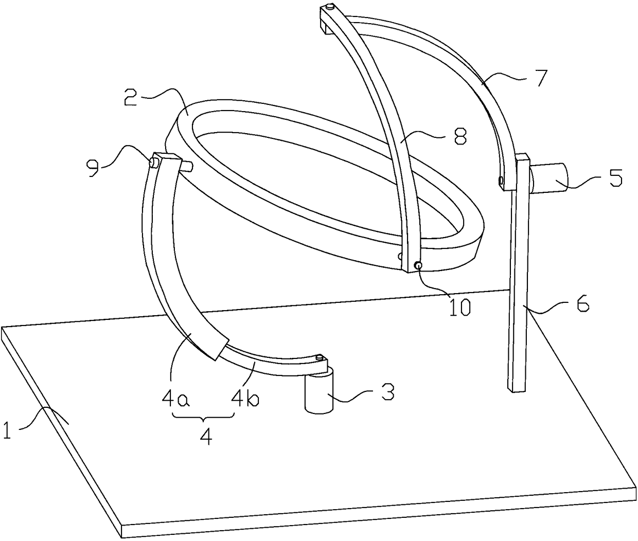
[0033] see figure 1 , a partially decoupled two-degree-of-freedom parallel mechanism, including a static platform 1, a dynamic platform 2, and a first kinematic branch chain and a second kinematic branch chain respectively connected between the static platform 1 and the dynamic platform 2;

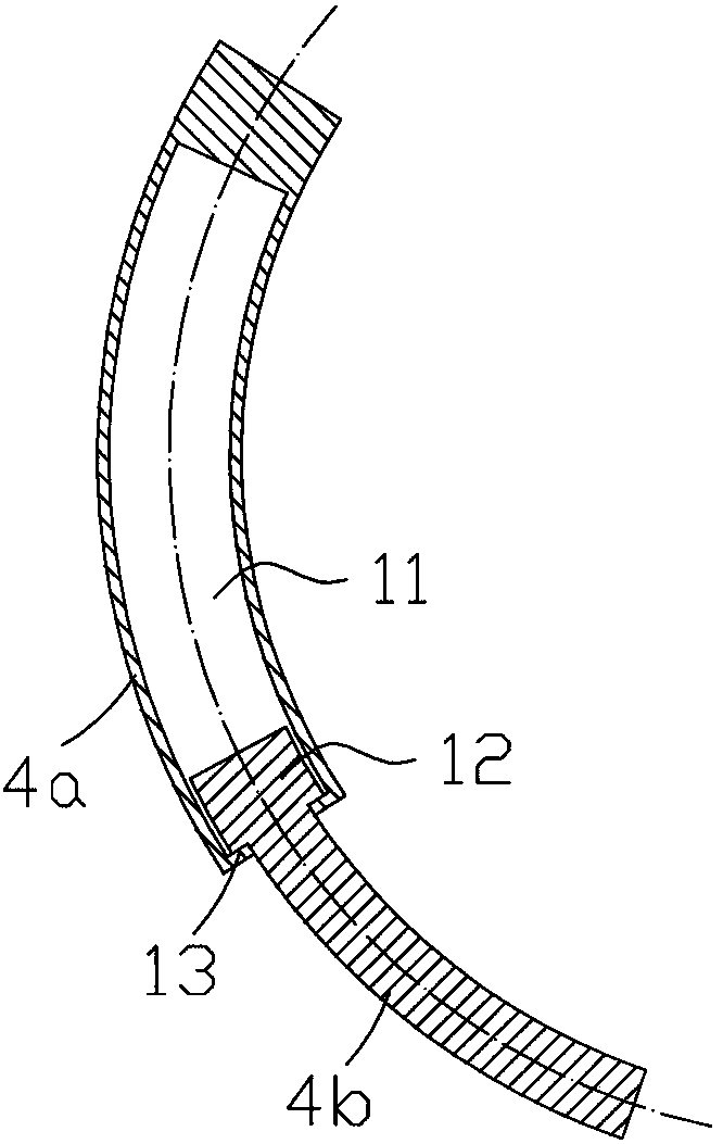
[0034] The first kinematic branch chain includes a first rotating pair 3, and the static platform 1 is rotationally connected to one end of the first arc-shaped connecting rod 4 through the first rotating pair 3, wherein the first arc-shaped connecting rod 4 is composed of two The first arc-shaped rod 4a arranged at the center of the arc and the second arc-shaped rod 4b are connected as a whole in a relatively sliding connection;

[0035] The second kinematic branch chain includes a second rotating pair 5, and a bracket 6 is provided on the static platform 1. The bracket 6 is rotationally connected with one end of the second arc connecting rod 7 through the second rotating pair 5, and the ...


PUM


Abstract

The invention discloses a partially-decoupled two-freedom-degree parallel mechanism. The partially-decoupled two-freedom-degree parallel mechanism comprises a stationary platform, a movable platform,a first moving branch chain and a second moving branch chain; the first moving branch chain comprises a first revolute pair; the stationary platform is rotationally connected with one end of a first arc-shaped connecting rod through the first revolute pair; the second moving branch chain comprises a second revolute pair; the stationary platform is provided with a bracket; the bracket is rotationally connected with one end of a second arc-shaped connecting rod through the second revolute pair; the other end of the second arc-shaped connecting rod is rotationally connected with one end of a third arc-shaped connecting rod; a first pin shaft and a second pin shaft which are arranged in a manner of forming an included angle of 90 degrees with each other are installed at the side surface of themovable platform; the other end of the first arc-shaped connecting rod is rotationally connected with the first pin shaft; and the other end of the third arc-shaped connecting rod is rotationally connected with the second pin shaft. The partially-decoupled two-freedom-degree parallel mechanism disclosed by the invention is simple in structure and high in flexibility, runs stably, realizes partialdecoupling of two rotation freedom degrees and can be applied to the fields of virtual machine tools, aviation simulation equipment, industrial robots, medical surgical equipment and the like.

Description

technical field [0001] The invention relates to a parallel mechanism, in particular to a partially decoupled two-degree-of-freedom parallel mechanism. Background technique [0002] Since the parallel mechanism was first proposed in 1938, it has been widely used in heavy-duty simulations due to its characteristics of large rigidity, strong bearing capacity, small error, high precision, small self-weight-to-load ratio, good dynamic performance, and easy control. Equipment, robots, CNC machine tools, sensors and micro-manipulation and other fields. [0003] At present, there are 2 degrees of freedom, 3 degrees of freedom, 4 degrees of freedom, 5 degrees of freedom, and 6 degrees of freedom parallel mechanisms. The drive units of these parallel mechanisms are coupled, that is, the movement of the overall output platform of the parallel robot in any direction is the synthesis of the movements of all drive units, and the movement of each drive unit is incompatible with the overal...

Claims


Application Information

Patent Timeline
IPC IPC(8): B25J9/00
CPCB25J9/0072
Inventor 肖新华
Owner HUBEI POLYTECHNIC UNIV
Why Eureka
Try Eureka