Sunken concrete mixing plant

A mixing station and concrete technology, applied in mixing plants, clay preparation devices, mixing operation control, etc., can solve the constraints of concrete mixing plant production capacity, popularization rate and regionality, unfavorable energy saving and emission reduction, reduce enterprise energy consumption, dust, Problems such as noise and vibration are difficult to isolate, so as to improve land use efficiency, facilitate dust collection, and shorten transmission distance

Pending Publication Date: 2018-08-03
BEIJING XIN YUAN NUO MEI ENVIRONMENTAL TECH CO LTD
View PDF0 Cites 2 Cited by
  • Summary
  • Abstract
  • Description
  • Claims
  • Application Information

AI Technical Summary

Problems solved by technology

[0004] (1) It is difficult to isolate dust, noise and vibration;
[0005] (2) The production efficiency is low. The actual performance of a 3-square unit with a nominal capacity of 180 cubic meters per hour is often around 50%, that is, the actual production capacity is only 90-100 cubic meters;
[0006] (3) It occupies a large area and the cost of land use is relatively high;
[0007] (4) High energy consumption, high cost, unavoidable spillage of materials during the lifting process, and the need to equip multiple people for cleaning and maintenance, which increases the labor cost of the enterprise;
[0008] (5) There are many and tall buildings on the ground, with obvious signs of industrial pollution, which are not in harmony with the surrounding environment of urban and rural construction planning, and the site selection range is small, making it difficult to supply materials nearby
[0009] In general, the existing equipment is not conducive to energy saving and emission reduction, reducing energy consumption of enterprises and improving production efficiency
At the same time, it is also necessary to consider the problems of earthquake resistance, wind speed, possible dumping and high-altitude operations brought about by the high height of the equipment, which leads to the limited shape and volume of each device, which greatly restricts the production capacity of the concrete mixing plant (building). , penetration and geographic

Method used


Image

  • Sunken concrete mixing plant
  • Sunken concrete mixing plant
  • Sunken concrete mixing plant

Examples


Embodiment Construction

[0026] The preferred embodiments of the present invention will be described in detail below with reference to the accompanying drawings.

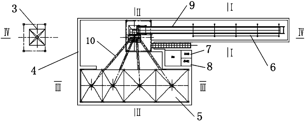
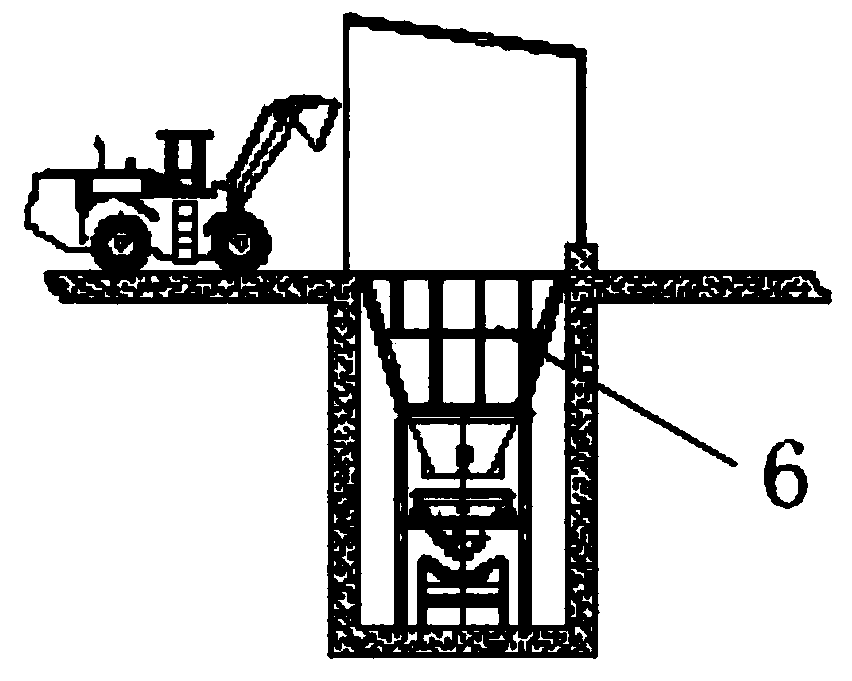
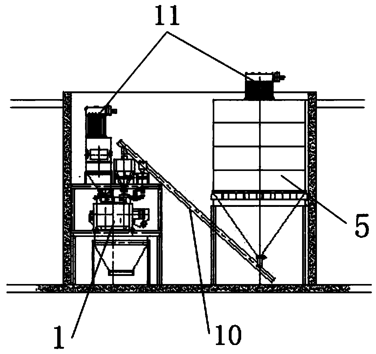
[0027] As shown in the figure, the present invention provides the following technical solutions: a sunken concrete mixing plant, including a storage system for storing materials, a mixing device 1 and a control system, and also includes a material lifting system 2 and a discharge device 3, so that The storage system and the stirring device 1 are arranged in the pit 4 below the ground, the control system and the unloading device 3 are arranged on the ground, and the stirring device 1 is connected to the unloading device 3 through the material lifting system 2 .

[0028] In this embodiment, the control system and the unloading device 3 are set on the ground, and the operator can control the lower operation through the monitoring system set in the pit and the control system on the ground without entering the pit, which improves the safety of th...


PUM


Abstract

The invention discloses a sunken concrete mixing plant. The sunken concrete mixing plant comprises a storage system for storing materials, a stirring device and a control system, and also comprises amaterial lifting system and an unloading device, wherein the storage system and the stirring device are arranged in pits under the ground, the control system and the unloading device are arranged on the ground, and the stirring device is connected to the unloading device through the material lifting system; the whole equipment is moved underground, so that aloft work above the ground is eliminated, the conveying condition of materials is changed, the initial material is conveyed horizontally, the material conveying distance is shortened, the material scattering condition is reduced, and the operating speed of the system is improved, and the number of workers is reduced. The whole system is more compactly arranged, and the energy consumption is saved and the work efficiency is further improved; the equipment is located underground to further form a closed space, so that dust is collected favorably, low frequency vibration can be also eliminated, noise pollution is reduced, and centralized control of pollution sources such as dust and noise is achieved.

Description

technical field [0001] The invention belongs to the field of mixing plants, and in particular relates to a sunken concrete mixing plant. Background technique [0002] Concrete mixing station (building) is a joint device used to centrally mix concrete, also known as concrete prefabrication field. Due to its high degree of mechanization and automation, its productivity is also high, and it can ensure the quality of concrete and save cement. It is often used in large and medium-sized water conservancy, electric power, bridges and other projects with large concrete engineering volume, long construction period, and concentrated construction sites. [0003] In the prior art, large-scale equipment such as concrete mixing plants (buildings), material storage devices, and mixing devices are relatively high on the ground. Although the tank trucks can be loaded with material by dropping, the powder tanks are built at high places, requiring For lifting and loading, aggregates such as s...

Claims


Application Information

Patent Timeline
Patent Type & Authority Applications(China)
IPC IPC(8): B28C9/02B28C9/00B28C7/00
CPCB28B15/00B28B17/00B28B17/04B28C7/00B28C9/00B28C9/02
Inventor 郝建华张胜富
Owner BEIJING XIN YUAN NUO MEI ENVIRONMENTAL TECH CO LTD
Why Eureka
Try Eureka