Interactive combination cantilever lifting scaffold
A technology for lifting and lowering scaffolding and scaffolding, applied in the field of scaffolding, can solve the problems of scaffolding, such as cost, material, time, unsafe, and heavy, and achieve the effects of reducing labor intensity, improving accuracy, and speeding up assembly speed.
- Summary
- Abstract
- Description
- Claims
- Application Information
AI Technical Summary
Problems solved by technology
Method used
Image

Examples
Embodiment 1
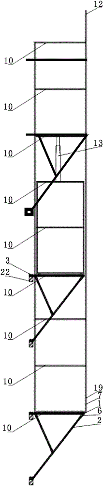
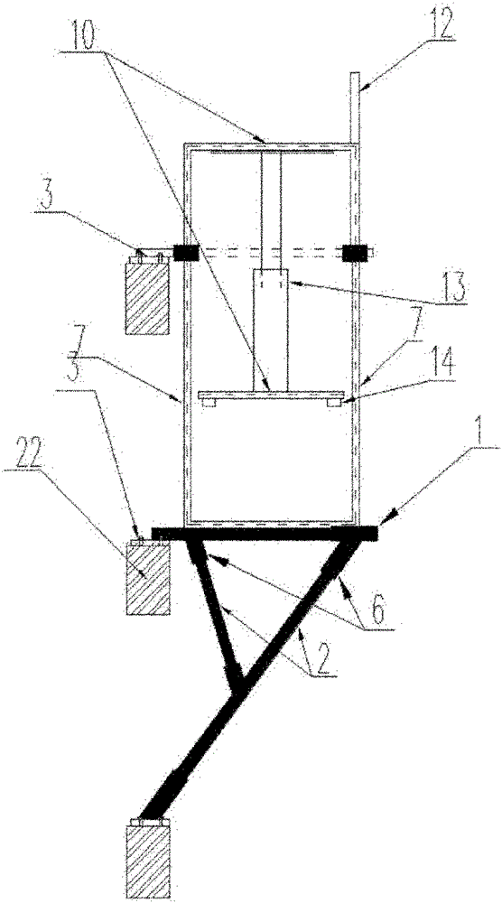
[0022] The support system is composed of a cantilever rod 1, a strut rod 2, a caliper 3, and a snap button 6. The caliper 3 is fixed on the beam 22, the cantilever rod 1 is fixed on the caliper 3, the strut 2 is connected with the cantilever rod 1 through a snap 6, and the other end is fixed on the caliper 3 on the next floor beam
[0023] In this embodiment, the workbench is composed of three working layers, and the construction site is assembled as follows: 1. The first layer of the pulley workbench and the first layer of the track workbench are alternately circled around the building, and the second layer of the pulley workbench is The first layer is placed on the first floor, the hydraulic cylinder 13 is fixed in the middle of the second floor frame side bar 10, and the third layer is placed on the hydraulic cylinder 13 and connected and fixed, and then placed four times below the frame side bar 10 of the first and second floors. Install the support valve 14 at each corner...
Embodiment 2
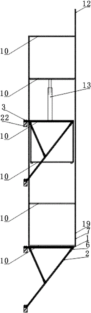
[0025] The support system is composed of a cantilever rod 1, a strut 2, a caliper 3, and a snap button 6. The caliper 3 is fixed on the beam 22, the cantilever rod 1 is fixed on the caliper 3, and one end of the brace 2 is fixed on the cantilever through the snap 6. On the rod 1, the other end is fixed on the caliper 3 on the beam of the next floor
[0026] In this embodiment, the workbench is composed of six working layer panels. According to the structure of the building, the required parts are processed and assembled on the construction site as follows: 1. The first layer of the pulley workbench and the first layer of the track workbench are sequentially assembled. Alternately arrange around the building for a week, and then put the second to fourth layers of the pulley workbench in sequence, install the hydraulic cylinder 13 in the middle of the frame side bar 10 on the fourth layer, and then connect and fix the fifth layer with the hydraulic cylinder. The sixth layer is p...
Embodiment 3
[0028] The support system is composed of a cantilever rod 1, a strut 2, a caliper 3, and a snap button 6. The caliper 3 is fixed on the beam 22, the cantilever rod 1 is fixed on the caliper 3, and one end of the brace 2 is fixed on the cantilever through the snap 6. On the rod 1, the other end is fixed on the caliper 3 on the beam of the next floor
[0029]In this embodiment, the workbench is composed of nine working layer panels, and the construction site is assembled as follows after the required parts are processed according to the structure of the building: 1. The first layer of the pulley workbench and the first layer of the track workbench Arrange alternately around the building for a week, and stack the second to sixth floors of the pulley workbench in sequence. 2. Fix the hydraulic cylinder 13 in the middle of the frame side bar 10 on the sixth floor of the pulley workbench, then connect the seventh floor of the pulley workbench to the hydraulic cylinder 13, and place ...
PUM
 Abstract
Description
Claims
Application Information
 - R&D
- Intellectual Property
- Life Sciences
- Materials
- Tech Scout
- Unparalleled Data Quality
- Higher Quality Content
- 60% Fewer Hallucinations
Browse by: Latest US Patents, China's latest patents, Technical Efficacy Thesaurus, Application Domain, Technology Topic, Popular Technical Reports.
© 2025 PatSnap. All rights reserved.Legal|Privacy policy|Modern Slavery Act Transparency Statement|Sitemap|About US| Contact US: help@patsnap.com