Turnover mechanism and detecting device for sectional material surface
A technology of overturning mechanism and detection equipment, which is applied in the direction of conveyors, conveyor objects, conveyor control devices, etc., which can solve the problems of low detection accuracy and low detection efficiency, and achieve the effect of ensuring accuracy and improving stability
- Summary
- Abstract
- Description
- Claims
- Application Information
AI Technical Summary
Problems solved by technology
Method used
Image

Examples
Embodiment 1
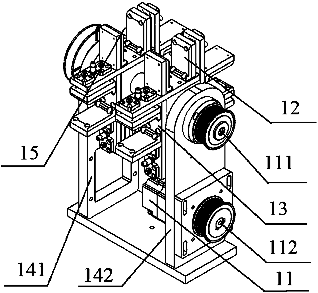
[0087] This embodiment provides a turning mechanism 1, such as figure 1 and figure 2 As shown, it includes: a first driver 11 , a clamping assembly 12 and a first bracket 13 .
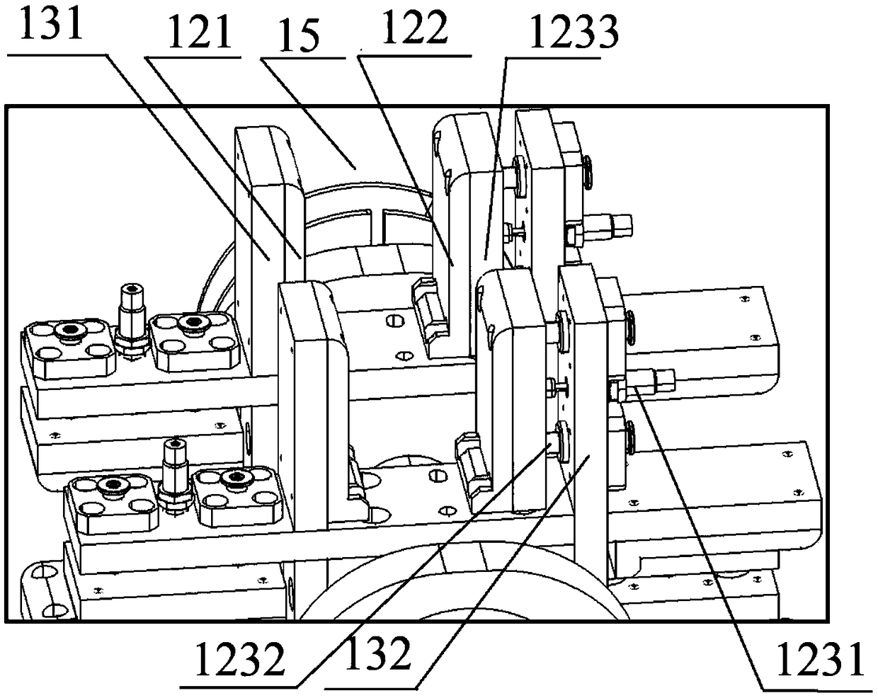
[0088] Wherein, the first driver 11 is provided with a first rotating shaft 111; the first bracket 13 is fixedly connected with the first rotating shaft 111, and the clamping assembly 12 is fixed on the first bracket 13; the above-mentioned clamping assembly 12 has opposite and parallel The first clamping head 121 and the second clamping head 122 are arranged, and the clamping space 15 with the opening facing outward is surrounded between the first clamping head 121 and the second clamping head 122; the first clamping head 121 and the second clamping head 122 A support 13 is fixedly installed. When the first driver 11 drives the clamping assembly 12 to rotate around the first rotation axis 111 , the opening of the clamping space 15 can be horizontal or vertical.
[0089] For example, the first rota...
Embodiment 2
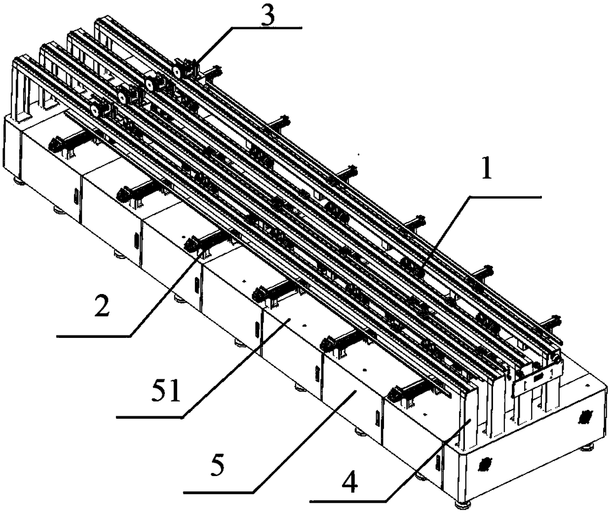
[0111] This embodiment provides a detection device for the profile surface, such as Figure 3 to Figure 12 As shown, it includes a detection platform 5, a conveying mechanism 2, a photographing device 3 and at least one pair of turning mechanisms 1 in Embodiment 1. There is a flat surface on the detection platform 5, and the conveying mechanism 2, the turning mechanism 1 and the photographing device 3 are all arranged on the detecting platform 5, and the conveying mechanism 2 slides and transmits along the sliding direction. The sliding direction in this embodiment is that the conveying mechanism 2 drives the profile The direction of movement from the feeding port 51 toward the feeding port. The turning mechanism 1 clamps and turns the profile, and detects the four outer surfaces of the profile to be tested through the camera device 3, which are: the first side wall 61, the second side wall 62, the third side wall 63 and the fourth side wall64.
[0112] Such as Figure 3 to...
Embodiment 3
[0153] The detection equipment for the surface of the profile provided in this embodiment, compared with the detection equipment for the surface of the profile provided in Example 2, is different in that:
[0154] In this embodiment, only one conveying mechanism 2 is provided, and two overturning mechanisms 1 are arranged, which are symmetrically arranged on both ends of the profile to clamp and overturn the end of the profile. The conveying mechanism 2 is arranged on the two overturning mechanisms 1, so that the profile is conveyed along the sliding direction.
[0155] As a further modification, the number of grippers 21 provided on the conveying mechanism 2 can be set to two, three, etc., to carry out the conveying of profiles corresponding to different conveying areas. For example, when three grippers 21 are set, each gripper 21 can be correspondingly arranged in the corresponding conveying area in Embodiment 2, and reciprocate along the first position to the third position...
PUM
 Abstract
Description
Claims
Application Information
 - R&D
- Intellectual Property
- Life Sciences
- Materials
- Tech Scout
- Unparalleled Data Quality
- Higher Quality Content
- 60% Fewer Hallucinations
Browse by: Latest US Patents, China's latest patents, Technical Efficacy Thesaurus, Application Domain, Technology Topic, Popular Technical Reports.
© 2025 PatSnap. All rights reserved.Legal|Privacy policy|Modern Slavery Act Transparency Statement|Sitemap|About US| Contact US: help@patsnap.com