Yarn cutting driving structure

A driving structure and yarn cutting technology, which is applied in textiles and papermaking, weft knitting, knitting, etc., can solve the problems of high production cost, difficulty in production and assembly, and economical reduction, so as to improve product economy and practicability, The effect of simplifying the internal structure and production process, reducing weight and production cost

Pending Publication Date: 2018-08-03
TANGSHAN WUGU ELECTROMECHANICAL EQUIP CO LTD
View PDF17 Cites 6 Cited by
  • Summary
  • Abstract
  • Description
  • Claims
  • Application Information

AI Technical Summary

Problems solved by technology

[0002] In the yarn cutting drive structure of the existing thread changer, the driving force for the action of the yarn clamping and cutting device comes from the knitting machine, or based on the rack and pinion transmission, the yarn clamping and cutting device is driven by the transmission parts such as the motor provided by the thread changer itself This type of yarn selection control structure is greatly reduced in economy due to the shortcomings of large volume, complex structure, cumbersome production process, difficult production and assembly, high production cost, and high failure rate in use.

Method used


Image

  • Yarn cutting driving structure
  • Yarn cutting driving structure
  • Yarn cutting driving structure

Examples


Embodiment Construction

[0035] The present invention will be further described below in conjunction with the examples, the purpose is only to better understand the contents of the present invention, therefore, the examples given do not limit the protection scope of the present invention.

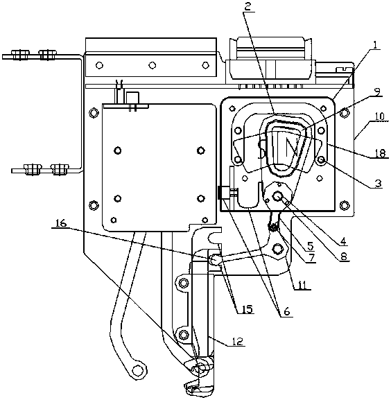
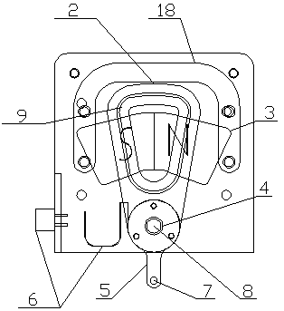
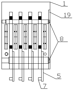
[0036] see figure 1 , figure 2 , image 3 , Figure 4 , Figure 5 , Figure 6 , Figure 7 , Figure 8 , Figure 9 , Figure 10 , Figure 11 , Figure 12 , Figure 13 , Figure 14 , Figure 15 , Figure 16 , Figure 17 , Figure 18 , a yarn cutting driving structure, including a yarn clamping and cutting device 12 and a driver housing 1 respectively arranged on the outer plate 10 of the thread changer, a yarn cutting lever 11 is installed on the outer plate 10 of the thread changer through a rotating shaft 8, and the yarn clamping Both the auxiliary yarn cutter 13 and the yarn pressing plate 14 of the yarn cutting device 12 are provided with a groove 15, and the yarn cutting lever 11 is provided wit...


PUM


Abstract

The invention relates to a wire changing device of a circular knitting machine, in particular to a yarn cutting driving structure. The yarn cutting driving structure comprises a yarn clamping and cutting device and a driver shell which are arranged on an outer plate of the wire changing device respectively, a swing arm is installed in the driver shell through a rotary shaft, permanent magnets areparallelly arranged at the two sides of the swinging arm, a coil is arranged on the swinging arm, the coil and the permanent magnets are parallelly placed to constitute a voice coil motor, and the swinging arm is driven by the voice coil motor to drive the yarn clamping and cutting device to complete the yarn clamping and cutting motion. By means of the wire changing device of the circular knitting machine, the internal structure and the production process are simplified, the brand-new sound coil motor is adopted, the yarn cutting driving structure is easy to manufacture and assemble, and theproduct economy and the practicability are improved.

Description

technical field [0001] The invention relates to a thread changer of a circular knitting machine, in particular to a yarn cutting drive structure. Background technique [0002] In the yarn cutting drive structure of the existing thread changer, the driving force for the action of the yarn clamping and cutting device comes from the knitting machine, or based on the rack and pinion transmission, the yarn clamping and cutting device is driven by the transmission parts such as the motor provided by the thread changer itself Action, this kind of yarn selection control structure has the disadvantages of large volume, complex structure, cumbersome production process, difficult production and assembly, high production cost, and high failure rate in use, which greatly reduces the economy. Contents of the invention [0003] The present invention aims to solve the above problems, thereby providing a yarn cutting drive structure that can simplify the internal structure and production p...

Claims


Application Information

Patent Timeline
Patent Type & Authority Applications(China)
IPC IPC(8): D04B15/60
CPCD04B15/60
Inventor 张燚
Owner TANGSHAN WUGU ELECTROMECHANICAL EQUIP CO LTD
Why Eureka
Try Eureka