
Sliding table type emissivity testing device

A test device and emissivity technology, which is applied in the field of instruments and meters, can solve the problems of unavailable, heavy labor, and insufficient temperature measurement range, and achieve the effects of improved accuracy, compactness, simplicity, and convenient operation

Inactive Publication Date: 2018-08-03
CHINA JILIANG UNIV
View PDF0 Cites 2 Cited by
  • Summary
  • Abstract
  • Description
  • Claims
  • Application Information

AI Technical Summary

Problems solved by technology

However, the currently obtained emissivity can only be a single or a few values, and a series of values ​​approximately from 0 to 1 cannot be obtained, and a specific emissivity cannot be directly obtained, which is labor-intensive and very inconvenient
[0004] There are not many devices for emissivity testing at this stage. The current technology has three shortcomings. First, the temperature measurement range is not wide enough to approximate from 0 to 1; second, within the working temperature range, the emissivity of the reference object is a fixed value or area The value cannot be adjusted continuously; the third is that the specific emissivity cannot be obtained directly, which affects the accuracy of the emissivity measurement

Method used


Image

  • Sliding table type emissivity testing device
  • Sliding table type emissivity testing device

Examples


Embodiment Construction

[0015] In order to make the object, technical solution and advantages of the present invention clearer, the present invention will be further described in detail below in conjunction with the accompanying drawings and embodiments. It should be understood that the specific embodiments described here are only used to explain the present invention, not to limit the present invention.

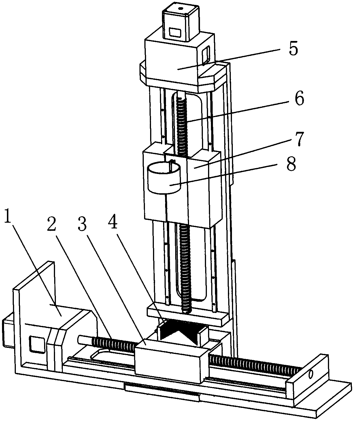
[0016] see figure 1 , figure 1 It is a structural schematic diagram of the present invention.

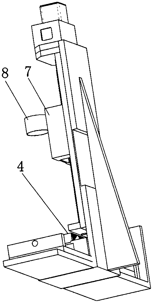
[0017] Sliding table type emissivity test device, including X motor 1, X axis 2, X translation stage 3, sample 4, Y motor 5, Y axis 6, Y translation stage 7, ring clamp 8, the X motor 1, X axis 2 It forms a whole with the X translation stage 3 and is located at the bottom; the sample 4 is placed on the X translation stage 3, and the Y motor 5, the Y axis 6, the Y translation stage 7 and the ring clamp 8 form a whole and are placed vertically on the X Translate above the 3 sets, the ring mouth of the r...


PUM


Abstract

The invention relates to a sliding table emissivity testing device. The sliding table emissivity testing device comprises an X motor, an X axis, an X translation stage, a sample, a Y motor, a Y axis,a Y translation stage and an annular clamp. The X-motor, the X-axis and the X translation table form a whole, which is located at the bottom; the sample is placed on the X translation table. The Y motor, the Y axis, the Y translation table and the ring clamp constitute a whole, which is placed vertically above the X translation table; the ring mouth of the annular clamp is just right above the sample. According to the invention, by designing a sliding table emissivity testing device, a relatively wide emissivity interval can be provided in the technical field of infrared temperature measurement, and a continuous optional surface unit is provided. The optional surface unit has a continuous and stable emittance in the working temperature range, and can also directly obtains the specific emissivity to improve the accuracy of measurement emissivity, The accuracy .is small and simple, and is convenient to operate.

Description

technical field [0001] The invention relates to the field of instruments and meters, in particular to an emissivity testing device. Background technique [0002] As a thermophysical parameter that can characterize the radiation ability of materials, emissivity plays an irreplaceable role in many high-tech fields. On the one hand, accurate emissivity data is closely related to basic research such as infrared technology. On the other hand, the study of emissivity has valuable research value in engineering technology fields such as industry, military affairs and aerospace. [0003] In the process of temperature measurement, in order to first determine the surface emissivity, a common auxiliary method is to use an object with known emissivity as a reference. However, the currently obtained emissivity can only be a single or a few values, and a series of values ​​approximately continuous from 0 to 1 cannot be obtained, and a specific emissivity cannot be directly obtained, whic...

Claims


Application Information

Patent Timeline
IPC IPC(8): G01J5/00
CPCG01J5/0003
Inventor 李文军王潇楠
Owner CHINA JILIANG UNIV
Learn More