Energy supply system usable under high voltage and energy supply method thereof

A high-voltage, energy-supply technology, applied in circuits, fuel cells, electrical components, etc., can solve problems such as complex design of energy supply systems and energy supply methods, low reliability, difficulty in meeting different energy demands of energy-demanding devices, and achieve Guaranteed continuity and stability, high reliability and simple structure

Inactive Publication Date: 2018-08-03
GLOBAL ENERGY INTERCONNECTION RES INST CO LTD
View PDF4 Cites 0 Cited by
  • Summary
  • Abstract
  • Description
  • Claims
  • Application Information

AI Technical Summary

Problems solved by technology

[0004] For this reason, what the present invention aims to solve is that the existing energy supply system and energy supply method have the defects of complex design, low reliability, and difficulty in meeting the different energy requirements of energy demand devices, and then provide a simple design, high reliability, and flexible energy Energy supply system and energy supply method that can be used under high voltage to meet different energy requirements of energy demand devices

Method used


Image

  • Energy supply system usable under high voltage and energy supply method thereof
  • Energy supply system usable under high voltage and energy supply method thereof
  • Energy supply system usable under high voltage and energy supply method thereof

Examples


Embodiment 1

[0059] This embodiment provides an energy supply method that can be used under high voltage, including the following steps:

[0060] Obtain high voltage insulating gas;

[0061] Delivering the high-voltage insulating gas to the inside of the fuel cell 2 through the insulating pipeline;

[0062] Electric energy is generated by the fuel cell 2 to supply energy for energy demand devices.

[0063] As an optional implementation, in this embodiment, the fuel cell is a hydrogen fuel cell; the high-voltage insulating gas includes hydrogen and oxygen; the energy-requiring device is a mechanical switch 1 .

[0064] In the above method, there is no need for external electric energy support or supplement, and there is no need for multi-stage voltage transformation. The design is simple and the reliability is high. By controlling the flow rate of high-voltage insulating gas and / or the number of fuel cells, and then controlling the output power, the energy demand can be flexibly met. Acco...

Embodiment 2

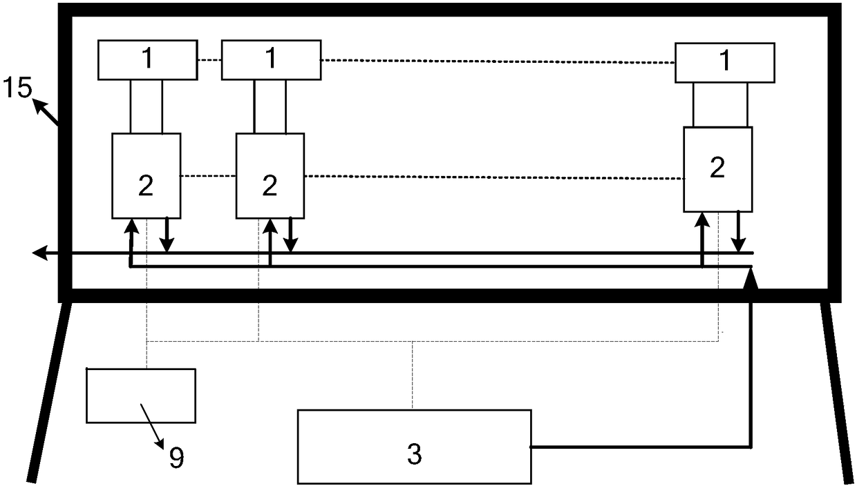
[0080] This embodiment provides an energy supply system that can be used under high voltage, such as figure 1 shown, including

[0081] The gas supply system 3 and the fuel cell 2, the gas supply system 3 and the fuel cell 2 are connected through insulating pipelines to supply gas to the inside of the fuel cell 2;

[0082] The energy demand device is connected with the fuel cell 2 to supply the energy demand device with the electric energy generated by the fuel cell 2 .

[0083] As an optional implementation, in this embodiment, the fuel cell is a hydrogen fuel cell; the energy demand device is a mechanical switch 1 , more preferably an electromagnetic relay.

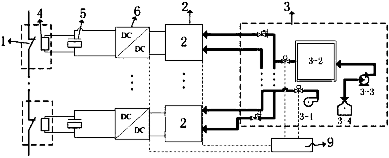
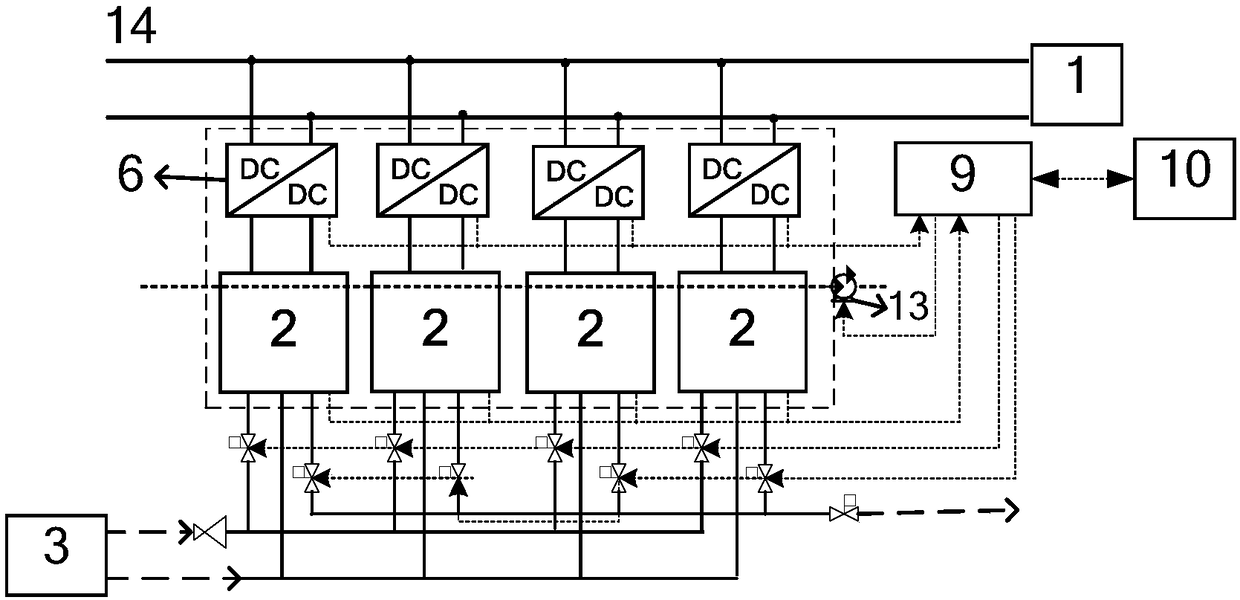
[0084] As an optional implementation, according to actual needs, the number of fuel cells 2 is n, and n is a positive integer. In this embodiment, as figure 2 As shown, the number of fuel cells 2 is one; in another embodiment, the number of fuel cells 2 is at least four, which are arranged in parallel with each other...


PUM


Abstract

The invention discloses an energy supply system usable under high voltage and an energy supply method thereof. The energy supply method comprises the following steps: acquiring high-voltage insulatinggas at first; then conveying the high-voltage insulating gas to the interior of a fuel cell through an insulated pipeline; and finally, generating electric energy via the fuel cell to supply energy to energy-demanding devices. Thus, external power support or supplementation is not need, and the need for multi-stage voltage transformation is eliminated. The energy supply system is simple in designand high in reliability; and by controlling the flow of high-voltage insulating gas and/or the number of the fuel cell, output power can be controlled, so the different energy demands of the energy-demanding devices can be flexibly met, and energy can be continuously supplied to the energy-demanding devices.

Description

technical field [0001] The invention belongs to the technical field of power electronic devices, and in particular relates to an energy supply system and an energy supply method that can be used under high voltage. Background technique [0002] Today, more and more situations are applicable in high-pressure environments, and the requirements are becoming more and more stringent. For example, high-voltage DC circuit breakers are mainly used in DC transmission and distribution lines to break the current of DC lines. In order to reduce the on-state loss and shorten the operating time of the circuit breaker, DC circuit breakers using a hybrid of mechanical switches and power electronic devices have received more and more attention, and a variety of topologies have been derived. In this type of DC circuit breaker, the mechanical switch branch through which the current flows is called the main branch, and the power electronic device branch used to break the current is called the ...

Claims


Application Information

Patent Timeline
Patent Type & Authority Applications(China)
IPC IPC(8): H01M8/04082H01M8/04089H02J1/10
CPCH01M8/04089H01M8/04201H02J1/10H02J2300/30Y02E60/50
Inventor 滕乐天邓占锋赵波刘锋梁丹曦
Owner GLOBAL ENERGY INTERCONNECTION RES INST CO LTD
Why Eureka
Try Eureka