Motor vehicle door lock

A technology for motor vehicle door locks and rotating lock forks, which is applied in the application of vehicle locks, building locks, and locks, etc., can solve problems such as occurrence of problems, component parts are not correctly connected to each other, support sleeve inclination position, damage, etc., and achieve simplification. Assembly effect

A technology for motor vehicle door locks and rotating lock forks, which is applied in the application of vehicle locks, building locks, and locks, etc., can solve problems such as occurrence of problems, component parts are not correctly connected to each other, support sleeve inclination position, damage, etc., and achieve simplification. Assembly effect

CN108368712BActive Publication Date: 2020-05-19KIEKERT AG

Image

  • Motor vehicle door lock
  • Motor vehicle door lock
  • Motor vehicle door lock

Examples


Embodiment Construction

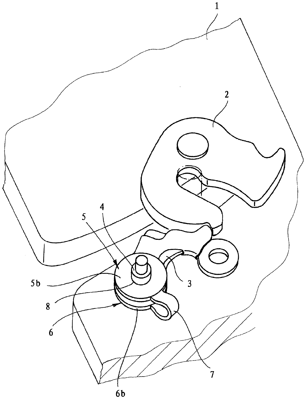
[0023] exist figure 1 A perspective view of a motor vehicle door lock is schematically shown in . The motor vehicle door lock has a housing 1 , which is currently designed as a metal lock box and in which, in the exemplary embodiment, a locking device 2 , 3 is mounted, which comprises a rotary locking fork 2 and a pawl 3 . In addition, further rods can also be mounted in the housing 1 , but this is not shown. Furthermore, instead of a metallic lock box as housing 1 , a housing cover made of plastic can also be used. This is likewise not shown. The lever, not shown, can be designed as a component of the actuating linkage and / or of the locking linkage.

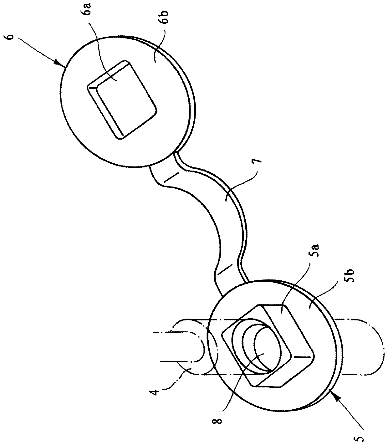
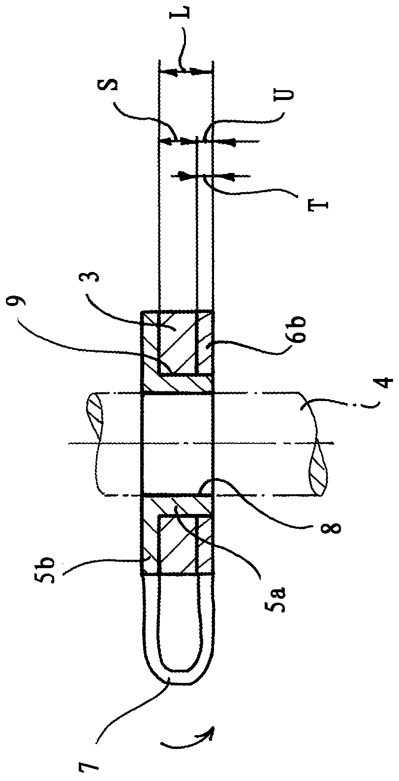
[0024] In this exemplary embodiment, a bearing pin 4 is provided for rotatably mounting the relevant locking device component 3 in the housing 1 . The locking device component 3 within the scope of the exemplary embodiment is the locking pawl 3 . In principle, it is also possible to mount the rotary locking fork 2 , which ...


PUM


Abstract

The invention relates to a motor vehicle door lock having a locking device (2, 3) which essentially comprises a rotary locking fork (2) and a locking pawl (3) as components (2, 3) of the locking device. Furthermore, at least one lever is provided as a component of the actuating and / or locking linkage. Furthermore, the motor vehicle door lock has at least one bearing pin (4) for supporting the associated locking device component (2, 3) and / or lever in the housing (1). In addition, there are support sleeves (5, 6, 7) which can be inserted into the opening (9) of the locking device component (3) and / or the rod, which support sleeve consists of at least two sleeves for the support pin (4). Elements (5, 6) constitute. According to the invention, one of the sleeve elements (5) has a plug seat (5a) extending through the opening (9). The plug receptacle (5a) engages substantially dimensionally stable into a plug receptacle (6a) of the other sleeve element (6).

Description

technical field [0001] The invention relates to a motor vehicle door lock comprising: a locking device which essentially comprises a rotary fork and a locking pawl as components of the locking device; at least one lever as part of an actuating lever system and / or a locking lever system Components; at least one support pin for rotatably supporting the relevant locking device member and / or lever in the housing; a supporting sleeve capable of being inserted into the opening of the locking device member and / or rod, the supporting sleeve comprising At least two sleeve elements for the support pin. Background technique [0002] In the case of the motor vehicle door lock according to DE 10 2012 108 882 A1, it is provided that the lever there is rotatably supported on the bearing pin in the housing with the bearing sleeve interposed therebetween. The bearing sleeve is mainly made of plastic and is integrally formed on the housing, which is likewise made of plastic. This results in...

Claims


Application Information

Patent Timeline
19 May 2020
Publication
CN108368712B
IPC
E05B79/08; E05B85/24; E05B15/16; E05B77/40
CPC
E05B77/40; E05B79/08; E05B85/24; E05B15/1635; E05B85/243
Inventors
T·巴德维茨