Fuel cell stack seal structure and production method therefor

A fuel cell stack and sealing structure technology, which is applied to fuel cell components, fuel cells, solid electrolyte fuel cells, etc., can solve the problems of damage to the first sealing component, difficulty in the interval between single cells, shortening of fuel cells, etc. damage effect

Active Publication Date: 2018-08-03
NISSAN MOTOR CO LTD
View PDF7 Cites 2 Cited by
  • Summary
  • Abstract
  • Description
  • Claims
  • Application Information

AI Technical Summary

Problems solved by technology

[0006] However, with the fuel cell described in Patent Document 1, when the molding resin is filled by injection molding, the molding resin is integrally bonded to the first sealing member, so the first sealing member may be damaged.
[0007] In addition, in the fuel cell described in the above-mentioned Patent Document 2, in order to reliably arrange the above-mentioned predetermined insulating structure, it is necessary to have a gap greater than a predetermined distance, and it is extremely difficult to shorten the distance between the fuel cells.

Method used


Image

  • Fuel cell stack seal structure and production method therefor
  • Fuel cell stack seal structure and production method therefor
  • Fuel cell stack seal structure and production method therefor

Examples


no. 1 approach

[0085] First, a fuel cell stack and a fuel cell module according to a first embodiment of the present invention will be described in detail with reference to the drawings. In addition, for convenience of description, the dimensional ratios of the drawings cited in the following embodiments are exaggerated and may differ from actual ratios.

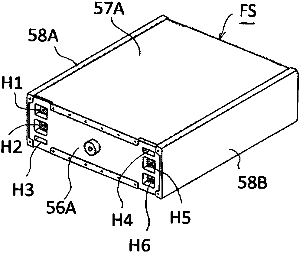
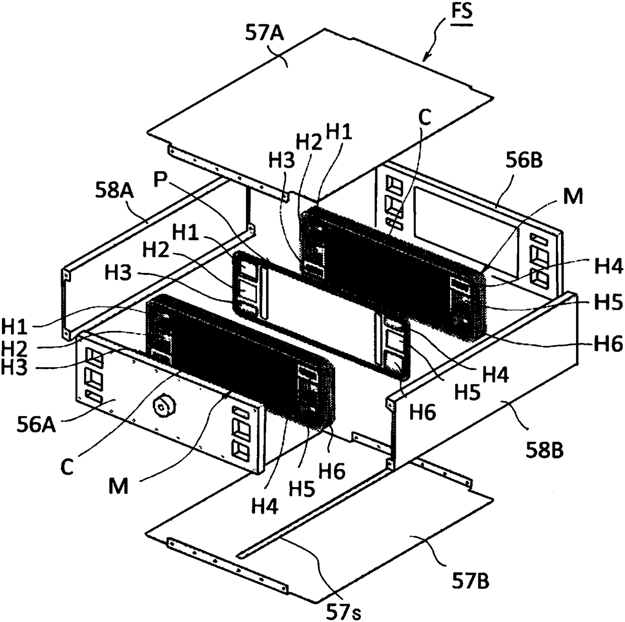
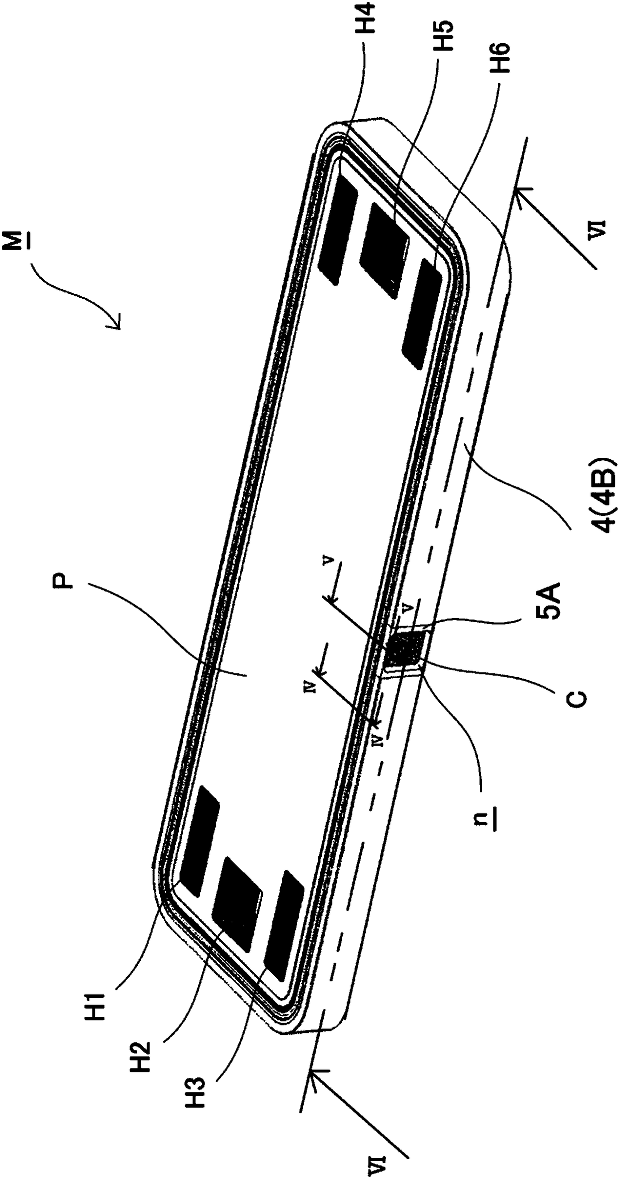
[0086] figure 1 It is a perspective view illustrating the fuel cell stack according to the first embodiment of the present invention. in addition, figure 2 It is a perspective view illustrating an exploded state of the fuel cell stack according to the first embodiment of the present invention. and, image 3 It is a perspective view showing the fuel cell module according to the first embodiment of the present invention. in addition, Figure 4 is along image 3 A schematic cross-sectional view of line IV-IV of the fuel cell module shown. and, Figure 5 is along image 3 A schematic cross-sectional view of the V-V line of the fuel c...

no. 2 approach

[0185] Next, a fuel cell module according to a second embodiment of the present invention will be described in detail with reference to the drawings. In addition, the fuel cell modules equivalent to the fuel cell modules described in the above-mentioned embodiments are denoted by the same reference numerals, and description thereof will be omitted.

[0186] Figure 10 (A) is a perspective view showing a fuel cell module according to a second embodiment of the present invention, Figure 10 (B) was Figure 10 (A) An enlarged view of a portion surrounded by line B of the fuel cell module shown in (A). Such as Figure 10 As shown, the difference between the fuel cell module M2 of this embodiment and the fuel cell module of the above-mentioned first embodiment is that the notch forming member 5A is covered by the outer peripheral sealing member 4 ( 4B).

[0187] In this embodiment, in addition to the effects obtained in the first embodiment described above, since the notch form...

no. 3 approach

[0189] Next, a fuel cell module according to a third embodiment of the present invention will be described in detail with reference to the drawings. In addition, the fuel cell modules equivalent to the fuel cell modules described in the above-mentioned embodiments are denoted by the same reference numerals, and description thereof will be omitted.

[0190] Figure 11 It is a perspective view showing a fuel cell module according to a third embodiment of the present invention. Such as Figure 11 As shown, the difference between the fuel cell module M3 of this embodiment and the fuel cell module of the above-mentioned first embodiment is that the outer peripheral sealing member 4 ( 4B) has a pair of plate-shaped notch forming members in the notch n 5B, the spacer has a protruding measurement terminal 23 extending along its planar direction, and the measurement terminal 23 is exposed at the notch n.

[0191] In this embodiment, in addition to the effects obtained in the first e...


PUM


Abstract

In the present invention, a fuel cell stack is configured by layering a plurality of fuel cell single cells, each having a membrane electrode joined body and a pair of separators sandwiching the membrane electrode joined body. This fuel cell stack seal structure comprises: an inner peripheral seal member plugging a gap between inner peripheral ribs, each protruding at least on the facing surface side of the pair of separators, at the peripheral edge portion of each of the separators; and an outer peripheral seal member plugging a gap between outer peripheral ribs, each protruding at least on the facing surface side of the pair of separators, at the outer peripheral side of the inner peripheral ribs. The inner peripheral seal member and the outer peripheral seal member form a first closed space between the inner peripheral seal member and the outer peripheral seal member. The outer peripheral seal member has a cut-out portion wherethrough the first closed space is in communication withthe exterior.

Description

technical field [0001] The invention relates to a sealing structure of a fuel cell stack and a manufacturing method thereof. Background technique [0002] Conventionally, as a fuel cell constituted by laminating a plurality of fuel cells, a configuration in which the peripheral portions of the plurality of fuel cells are integrally bonded by injection molding resin over the circumferential direction has been proposed (see Patent Document 1). [0003] In addition, as a fuel cell configured by laminating a plurality of fuel cells, a configuration has been proposed in which a predetermined insulating structure is provided at the periphery between the plurality of fuel cells (see Patent Document 2). [0004] Patent Document 1: Japanese Unexamined Patent Publication No. 2006-092924 [0005] Patent Document 2: International Publication No. 2014 / 174944 [0006] However, in the fuel cell described in Patent Document 1, when the molding resin is filled by injection molding, the mol...

Claims


Application Information

Patent Timeline
Patent Type & Authority Applications(China)
IPC IPC(8): H01M8/0271H01M8/02H01M8/0202H01M8/10H01M50/77
CPCH01M8/0271H01M8/1004H01M8/241H01M8/0254H01M8/026H01M8/0286H01M2008/1095H01M8/0276Y02P70/50Y02E60/50H01M8/2465
Inventor 关根谦克沼尾康弘市原敬士屋隆了宫冈浩
Owner NISSAN MOTOR CO LTD
Why Eureka
Try Eureka