
A pig feed automatic feeder

A feeder, pig feed technology, applied in animal feeding devices, applications, animal husbandry, etc., can solve problems such as pollution and exposure to the outside world, and achieve the effect of reducing labor, reducing labor, and ensuring cleanliness

Active Publication Date: 2020-11-24
道真仡佬族苗族自治县兴康生态特种养殖有限公司
View PDF5 Cites 0 Cited by
  • Summary
  • Abstract
  • Description
  • Claims
  • Application Information

AI Technical Summary

Problems solved by technology

[0004] The present invention intends to provide an automatic pig feed feeder to solve the problem that the feeding trough is exposed to the outside world when it is set in the pig house and is easily polluted when not in use

Method used


Image

  • A pig feed automatic feeder
  • A pig feed automatic feeder
  • A pig feed automatic feeder

Examples


Embodiment 1

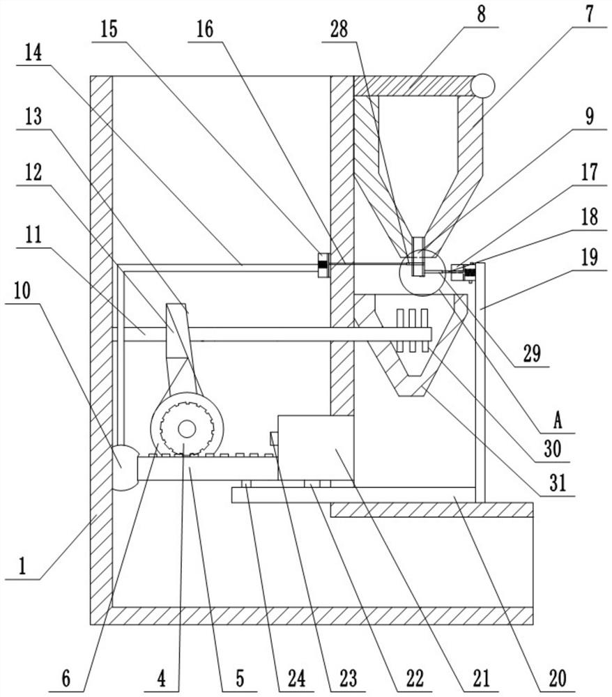
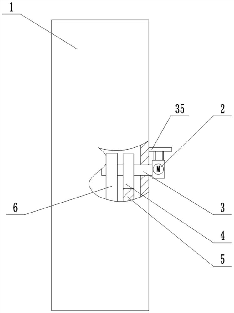
[0030] Basic as attached figure 1 And attached figure 2 Shown: an automatic feeder for pig feed, including an "L"-shaped body 1 and a funnel-shaped feed box 7 welded on the top of the body 1 . The opening above the funnel-shaped feed box 7 is hinged with a baffle 8 through a pin shaft, which can prevent external dust from entering the funnel-shaped feed box 7 and prevent the feed in the funnel-shaped feed box 7 from being exposed to the air for a long time and easily polluted , To a certain extent, ensure the cleanliness of the feed. The funnel-shaped feed box 7 is a transparent funnel-shaped feed box 7, which can make things convenient for the cultivators to observe the amount of feed in the funnel-shaped feed box 7, and immediately pour the feed inward to ensure the normal operation of the machine.

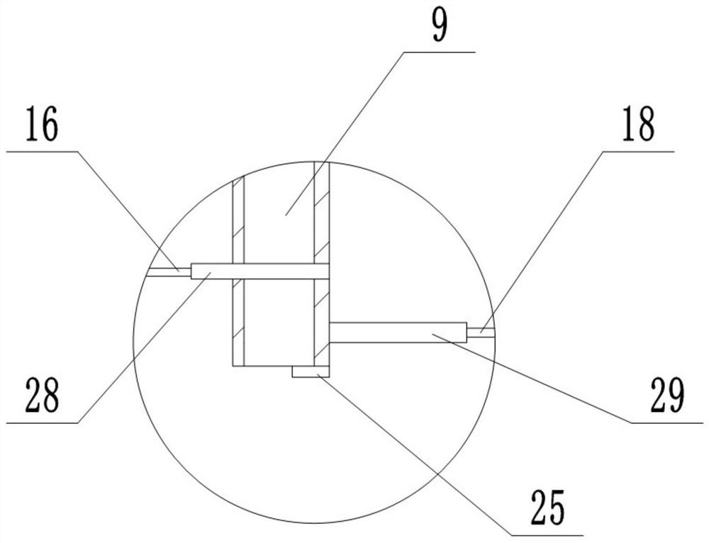
[0031] The lower end of the funnel-shaped feed box 7 is connected with a discharge pipe 9 communicating with it, and the discharge pipe 9 is provided with a first valve plate...

Embodiment 2

[0047] The difference between this embodiment and the above embodiment is that, as attached Figure 5 And attached Figure 6 As shown, the blocking portion on the right side of the opening of the lower end of the discharge pipe 9 is an elastic arc groove 32 for receiving feed, the right end of the elastic arc groove 32 is hinged with the right side of the lower end of the discharge pipe 9, and the left end is an opening. shape and does not contact the lower end of the discharge pipe to form a seal.

[0048] A squeeze rod 34 is hinged at the opening of the left end of the elastic arc-shaped groove 32 , and a push rod 33 is welded at the lower side of the first valve plate 28 . Both the extruding rod 34 and the elastic arc-shaped groove are respectively connected between the side walls of the discharge pipe through extension springs.

[0049] When the first valve plate 28 moved to the left to open the discharge pipe 9, the elastic arc-shaped groove at this moment was attached....


PUM


Abstract

The invention relates to the technical field of livestock raising machines and particularly discloses an automatic feeder of pig feed. The automatic feeder comprises a body and a hopper-shaped feed box fixedly connected to the top of the body, wherein a discharging pipe is communicated under the hopper-shaped feed box; a first valve plate is arranged at the discharging pipe; a forwards-rotating and reversely-rotating motor is arranged on the outer side wall of the body; an output shaft in the forwards-rotating and reversely-rotating motor is connected with a gear by a rotary rod; a sliding guide rail is fixedly connected to a platform of the body and is connected with a rack meshed with the gear in a sliding manner; one end of the rack is fixedly connected with a feed intake groove which is connected with the sliding guide rail in a sliding manner; an elastic air bag is adhered to the inner side wall of the body; the free end of the rack is contacted with the elastic air bag in an extruding manner; the elastic air bag is communicated with a first cylinder by an air transmission pipe; one end of a first piston rod is connected with the first valve plate. The automatic feeder disclosed by the invention has the advantage that the problem that the feed intake groove is exposed outside when being arranged in a piggery and is easily polluted when being not used is solved.

Description

technical field [0001] The invention relates to the technical field of animal husbandry machinery, and specifically discloses an automatic feeder for pig feed. Background technique [0002] With the continuous improvement of people's living standards, there are more and more requirements for the quantity of pork. In breeding, in order to meet its growth needs, it is fed after stirring various raw materials every day. [0003] In the process of pig breeding, the management of the feeding process of pigs is a key link, which is directly related to the quality of breeding and economic benefits; for large farmers, a complete breeding system is needed, and the funds of large farmers are relatively abundant , but small-scale farmers have to manually add pig food to the pig trough every time they feed the pigs. This is not only inefficient, but also causes a large amount of labor for the breeders, which is unfavorable for large-scale breeding. Moreover, the troughs for holding pi...

Claims


Application Information

Patent Timeline
Patent Type & Authority Patents(China)
IPC IPC(8): A01K5/02
CPCA01K5/02A01K5/0225
Inventor 冯举
Owner 道真仡佬族苗族自治县兴康生态特种养殖有限公司
Learn More