Automatic feeder of pig feed
A feeder, pig feed technology, applied in animal feeding devices, applications, animal husbandry, etc., can solve the problems of exposure to the outside world, pollution, etc., and achieve the effect of reducing labor, reducing labor, and ensuring cleanliness
- Summary
- Abstract
- Description
- Claims
- Application Information
AI Technical Summary
Problems solved by technology
Method used
Image
Examples
Embodiment 1
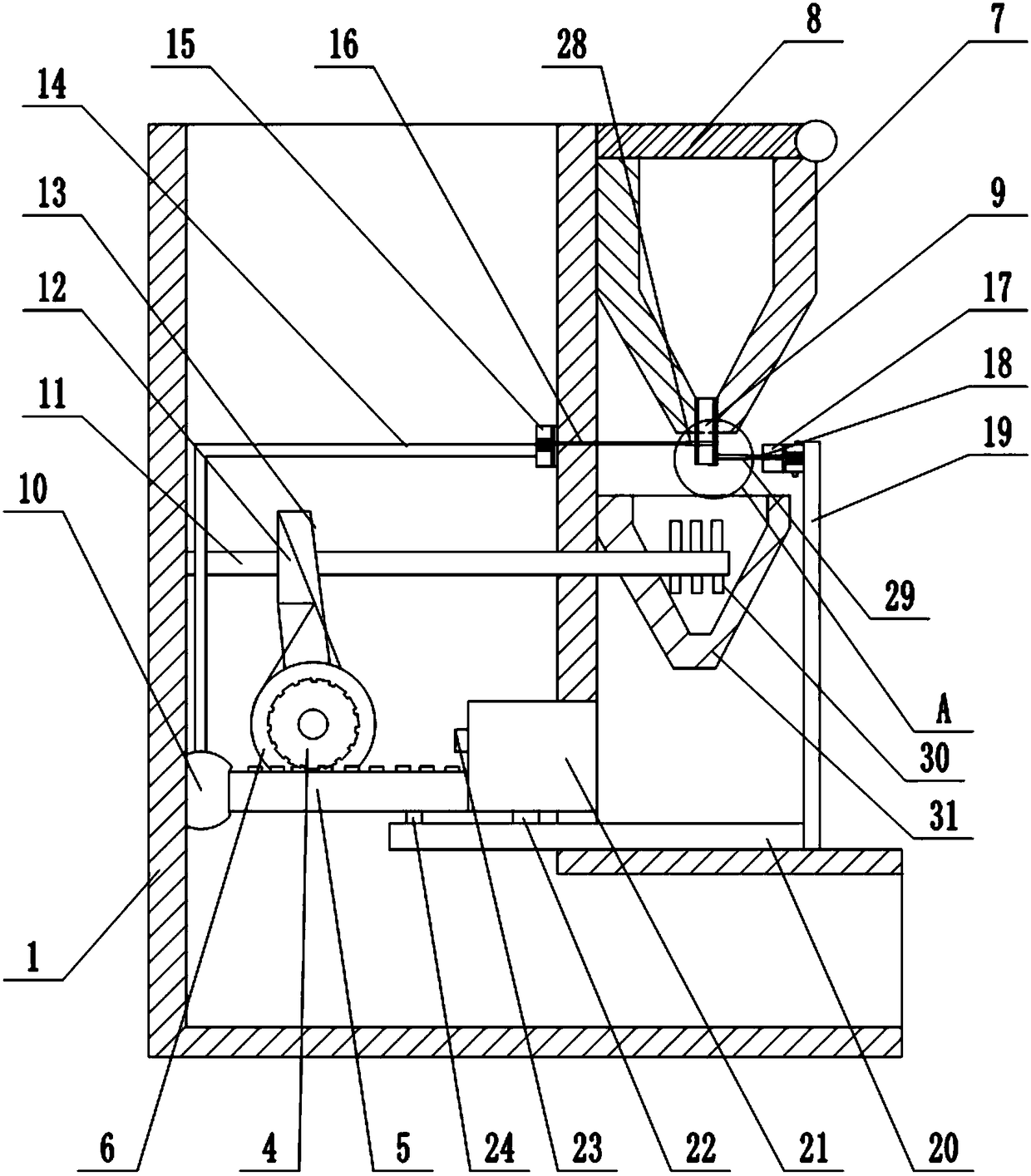
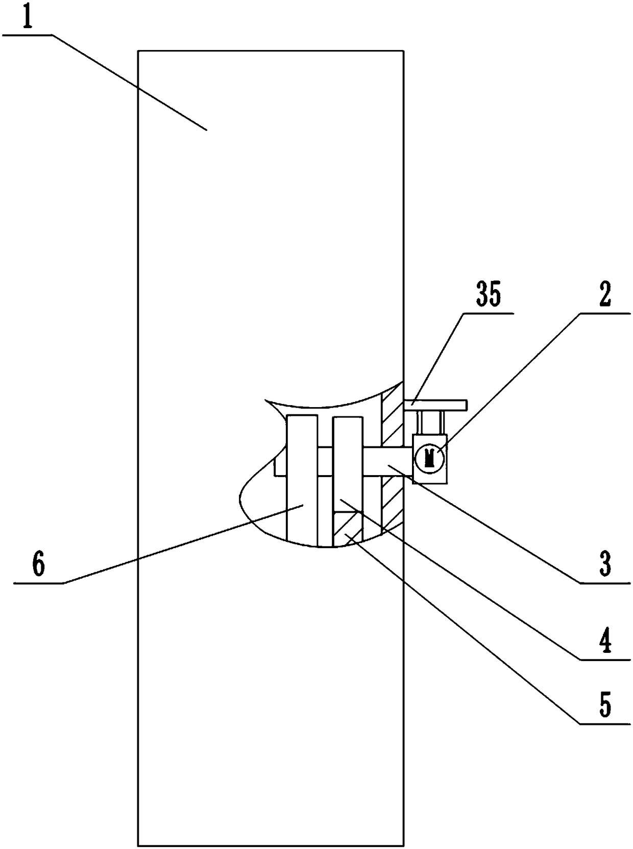
[0030] Basic as attached figure 1 And attached figure 2 Shown: an automatic feeder for pig feed, including an "L"-shaped body 1 and a funnel-shaped feed box 7 welded on the top of the body 1 . The opening above the funnel-shaped feed box 7 is hinged with a baffle plate 8 through a pin shaft, which can prevent external dust from entering the funnel-shaped feed box 7, and prevent the feed in the funnel-shaped feed box 7 from being exposed to the air for a long time and easily polluted , To a certain extent, ensure the cleanliness of the feed. The funnel-shaped feed box 7 is a transparent funnel-shaped feed box 7, which can make things convenient for the cultivators to observe the amount of feed in the funnel-shaped feed box 7, and immediately pour the feed inward to ensure the normal operation of the machine.
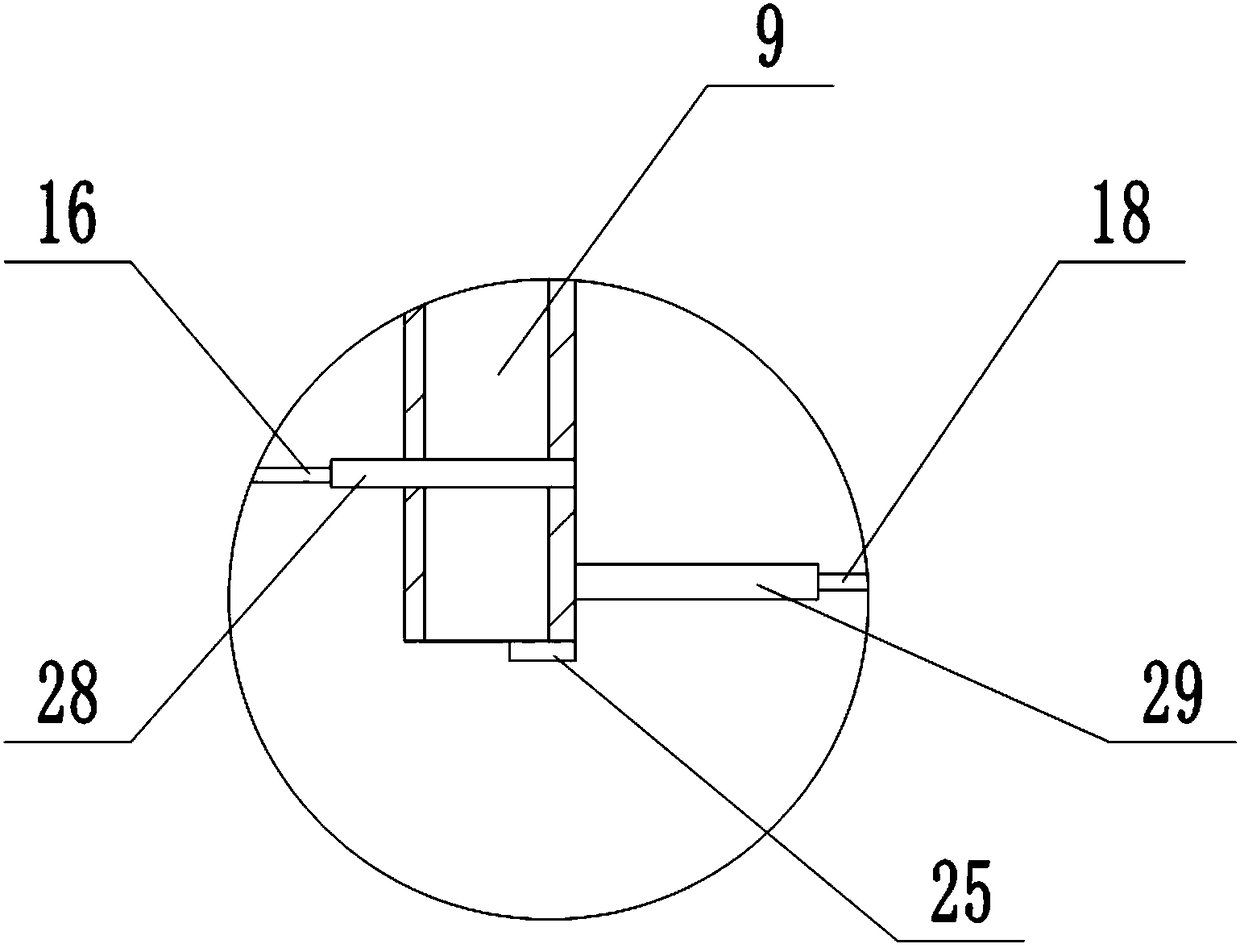
[0031] The lower end of the funnel-shaped feed box 7 is connected with a discharge pipe 9 communicating with it, and the discharge pipe 9 is provided with a first valv...
Embodiment 2
[0047] The difference between this embodiment and the above embodiment is that, as attached Figure 5 And attached Image 6 As shown, the blocking portion on the right side of the opening of the lower end of the discharge pipe 9 is an elastic arc groove 32 for receiving feed, the right end of the elastic arc groove 32 is hinged with the right side of the lower end of the discharge pipe 9, and the left end is an opening. shape and does not contact the lower end of the discharge pipe to form a seal.
[0048] The left end opening of the elastic arc groove 32 is hinged with an extruding rod 34, and the lower side of the first valve plate 28 is welded with a push rod 33. The push rod 33 and the elastic arc-shaped groove are both distributed and connected between the extension spring and the side wall of the discharge pipe.
[0049] When the first valve plate 28 moved to the left to open the discharge pipe 9, the elastic arc-shaped groove at this moment was attached. Image 6 sta...
PUM
 Abstract
Description
Claims
Application Information
 - R&D
- Intellectual Property
- Life Sciences
- Materials
- Tech Scout
- Unparalleled Data Quality
- Higher Quality Content
- 60% Fewer Hallucinations
Browse by: Latest US Patents, China's latest patents, Technical Efficacy Thesaurus, Application Domain, Technology Topic, Popular Technical Reports.
© 2025 PatSnap. All rights reserved.Legal|Privacy policy|Modern Slavery Act Transparency Statement|Sitemap|About US| Contact US: help@patsnap.com


