Industrial batch packaging equipment for light emitting diodes

A technology of light-emitting diodes and packaging equipment, applied in the directions of packaging, transportation and packaging, multiple packages, etc., can solve the problem of not being able to automatically package light-emitting diodes in batches, achieve intermittent automatic cutting, reduce manual edge sealing operations, Reduce the effect of manual sealing operations

Pending Publication Date: 2022-05-27
深圳市荣晟泰科技有限公司
View PDF10 Cites 2 Cited by
  • Summary
  • Abstract
  • Description
  • Claims
  • Application Information

AI Technical Summary

Problems solved by technology

[0005] In order to overcome the shortcomings of the existing LED packaging device that cannot automatically pack LEDs in batches, the technical problem to be solved is to provide an industrial batch packaging equipment for LEDs with automatic loading and edge sealing

Method used


Image

  • Industrial batch packaging equipment for light emitting diodes
  • Industrial batch packaging equipment for light emitting diodes
  • Industrial batch packaging equipment for light emitting diodes

Examples


Embodiment 1

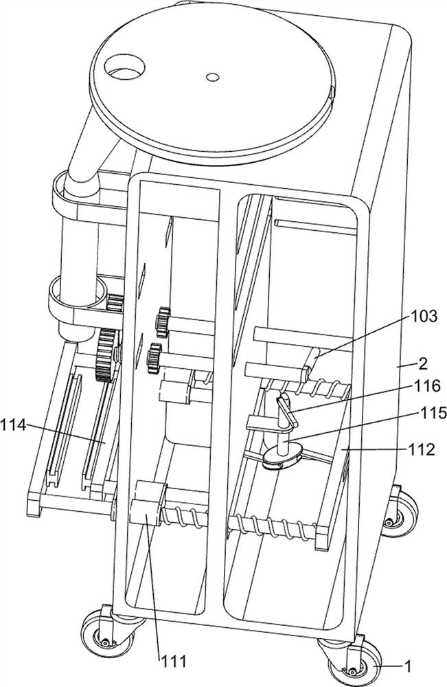
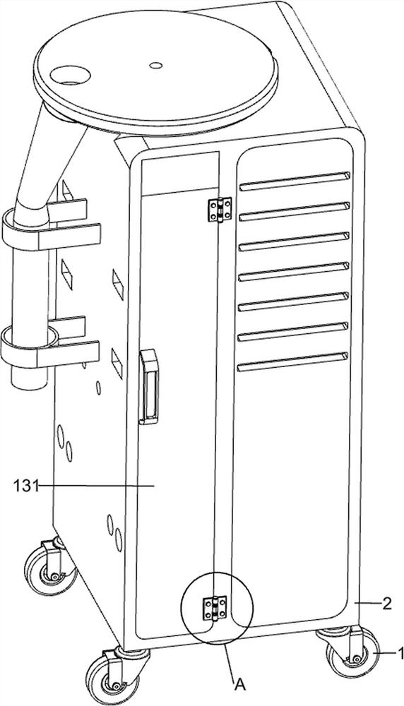
[0035] An industrial batch packaging equipment for light-emitting diodes, such as figure 1 , figure 2 and image 3As shown, it includes a roller 1, a tool box 2, a feeding rack 3, a loader 4, a feeding tube 5, an upper limit frame 6, a lower limit frame 61, a device frame 7, an intermittent diode feeding mechanism 8, and a packaging mechanism 9. The pulling mechanism 10 and the splitting mechanism 11, the left and right sides of the bottom of the toolbox 2 are provided with rollers 1 that rotate symmetrically forward and backward, the top left of the toolbox 2 is provided with a feeding rack 3, and the right side of the top of the feeding rack 3 is connected with a The feeder 4, the bottom of the feeding rack 3 are connected with a lowering pipe 5, the upper left part of the tool box 2 is provided with an upper limit frame 6 and a lower limit frame 61, the lower limit frame 61 is located below the upper limit frame 6, and the upper limit frame 6 is Horizontal N shape, the s...

Embodiment 2

[0042] On the basis of Example 1, as image 3 and Figure 13 As shown, it also includes a toughness increasing mechanism 12. The toughness increasing mechanism 12 includes a sliding frame 121, a fifth fixing frame 122, a third tension spring 123 and a pressing shaft 124. The left part of the device frame 7 is provided with sliding frames on both sides. 121. The lower part of the sliding frame 121 is provided with a fifth fixing frame 122, a lower pressing shaft 124 is slidably connected between the fifth fixing frames 122, and a third tension spring 123 is wound around the lower part of the fifth fixing frame 122, and the third tension spring 123 The two ends are respectively connected with the fifth fixing frame 122 and the pressing shaft 124 .

[0043] The rolled packaging film is sleeved on the left end of the device frame 7, and then the packaging film is pulled out to make it bypass the bottom of the pressing shaft 124, the top of the device frame 7, and the bottom of th...


PUM


Abstract

The invention relates to industrial batch packaging equipment, in particular to industrial batch packaging equipment for light emitting diodes. The invention provides industrial batch packaging equipment for light-emitting diodes with automatic loading and edge sealing functions. Industrial batch packaging equipment for light-emitting diodes comprises idler wheels, a tool box, a feeding frame, a loading device, a discharging pipe, an upper limiting frame, a lower limiting frame, a device frame and the like, the idler wheels are rotationally arranged on the left side and the right side of the bottom of the tool box in a front-back symmetrical mode, the feeding frame is arranged on the left side of the top of the tool box, and the right side of the top of the feeding frame communicates with the loading device; the bottom of the feeding frame communicates with a discharging pipe, an upper limiting frame and a lower limiting frame are arranged on the upper left portion of the tool box, and a device frame is arranged on the upper left portion of the tool box. And the third packaging device and the second packaging device can intermittently and transversely clamp and package the middle of the packaging film, the effect of automatically packaging the top and bottom edges of the packaging bag is achieved, and manual sealing operation is reduced.

Description

technical field [0001] The invention relates to an industrial batch packaging device, in particular to an industrial batch packaging device for light emitting diodes. Background technique [0002] Light-emitting diodes are light-emitting devices that efficiently convert electrical energy into light energy. They are widely used in lighting fields, such as LED lighting, flat-panel displays, etc. According to the changes in light emission, light-emitting diodes can also be subdivided into monochromatic light-emitting diodes and infrared light-emitting diodes. , color-changing light-emitting diodes, etc. After the factory produces light-emitting diodes, they need to be packaged for easy flow into the market. [0003] Patent application CN213009458U, published on 20210420, discloses an LED light-emitting diode packaging device, in particular to the technical field of diode packaging equipment, including a casing, a protective casing is wrapped and fixed on the outside of the casi...

Claims


Application Information

Patent Timeline
Patent Type & Authority Applications(China)
IPC IPC(8): B65B9/06
CPCB65B9/06
Inventor 谢泽璇
Owner 深圳市荣晟泰科技有限公司
Why Eureka
Try Eureka