Equipment for printing and stamping bottle caps

A technology of equipment and bottle caps, applied in the field of stamping equipment, can solve problems such as affecting stamping efficiency, and achieve the effect of improving efficiency

Inactive Publication Date: 2020-11-13
黄春燕
View PDF1 Cites 2 Cited by
  • Summary
  • Abstract
  • Description
  • Claims
  • Application Information

AI Technical Summary

Problems solved by technology

[0005] In order to overcome the need to manually place the bottle cap in the equipment for stamping, thus prolonging the stamping process and affecting the stamping efficiency, the technical problem to be solved is to provide a printing stamping that can automatically unload the material during the printing stamping process bottle cap equipment

Method used


Image

  • Equipment for printing and stamping bottle caps
  • Equipment for printing and stamping bottle caps
  • Equipment for printing and stamping bottle caps

Examples


Embodiment 1

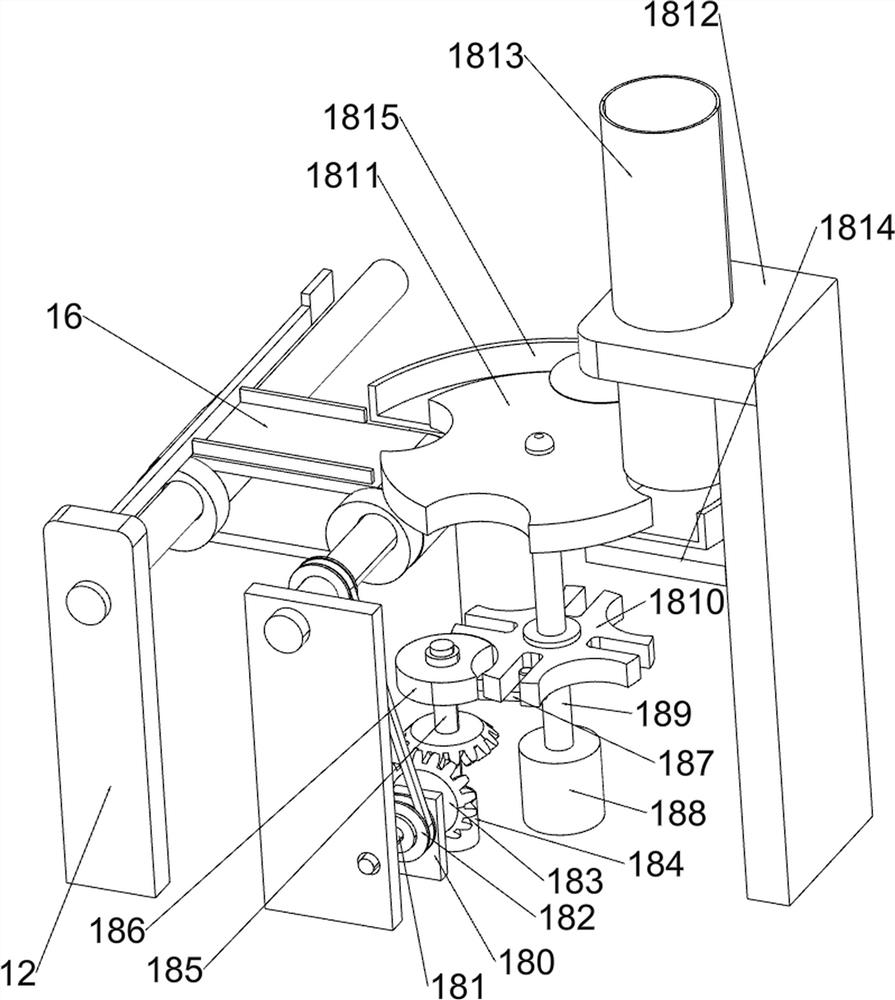
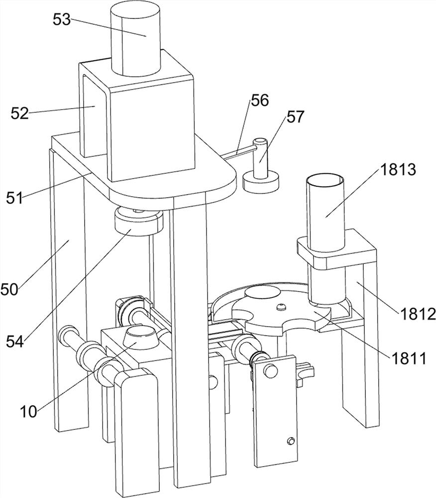
[0023] A device for printing and stamping bottle caps, such as figure 1 with Figure 3-5 As shown, it includes a bottom plate 1, a first support frame 2, a servo motor 3, a first bearing seat 4, a second bearing seat 41, a printing stamping mechanism 5, a first rotating shaft 6, a first conveyor belt 7, and a first protective frame 8. , The third support frame 9, the punch 10, the conveying mechanism 11, the third bearing seat 12, the fourth shaft 13, the second protection frame 14, the fifth shaft 15, the second conveyor belt 16, the second pulley assembly 17, and the blanking The mechanism 18, the ninth shaft 19, the rotating plate 20 and the fourth belt pulley assembly 21, the bottom left of the bottom plate 1 is provided with a first support frame 2, the upper part of the first support frame 2 is provided with a servo motor 3, the bottom left There is a first bearing seat 4, the first bearing seat 4 is located on the front side of the first support frame 2, the upper left fr...

Embodiment 2

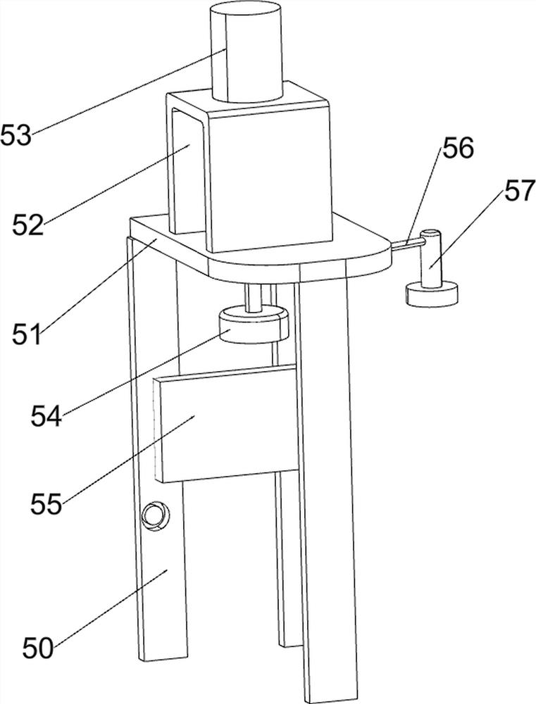
[0026] On the basis of Example 1, such as Figure 2-6 As shown, the printing and punching mechanism 5 includes a first support plate 50, a second support plate 51, a second support frame 52, a cylinder 53, a die 54, a connecting plate 55, a connecting rod 56 and a printing block 57. The upper middle of the bottom plate 1 There are three first support plates 50, the three first support plates 50 are provided with a second support plate 51, the upper part of the second support plate 51 is provided with a second support frame 52, and the upper part of the second support frame 52 is provided with an air cylinder 53. The cylinder 53 passes through the second support plate 51 and the second support frame 52. The lower part of the cylinder 53 is provided with a concave mold 54 which is located on the lower side of the second support plate 51. The right part of the cylinder 53 is provided with a connecting rod 56 and a connecting rod 56 A printing block 57 is provided on the right, a c...


PUM


Abstract

The invention relates to stamping equipment, in particular to equipment for printing and stamping bottle caps. The technical problem to be solved is to provide the equipment for printing and stampingthe bottle caps, which can automatically discharge in the printing and stamping process. The equipment for printing and stamping the bottle caps comprises a bottom plate, a first supporting frame, a servo motor and a first bearing seat, wherein the bottom plate is used for mounting the whole equipment; the first supporting frame is arranged on one side of the upper part of the bottom plate; the servo motor is arranged on the first supporting frame; and the first bearing seat is arranged on the side, close to the first supporting frame, of the upper portion of the bottom plate. According to theequipment, the effect of automatic discharging in the printing and stamping process is achieved, bottle caps to be printed and stamped are placed in a discharging pipe, then a third rotating disc rotates continuously, the bottle caps at the bottommost end in the discharging pipe are moved to a second conveying belt, and therefore the effect of automatic discharging can be achieved.

Description

Technical field [0001] The invention relates to a punching device, in particular to a device for printing and punching bottle caps. Background technique [0002] Bottle caps can be seen everywhere in people’s daily life. There are many types of bottle caps, which are basically used for sealing. The most common bottle caps are made of aluminum or plastic. The bottle caps are used to seal bottles. Different functions, the bottle cap has the ability to keep the contents tightly closed. In the process of making bottle caps, manufacturers usually print the production date and product brand on the caps, and at the same time stamp the caps to facilitate the later fit between the caps and the mouth, so that consumers can obtain them through the caps Certain product information. [0003] Existing stamping equipment, such as the Chinese patent with patent publication number CN203976355U, discloses a bottle cap stamping pre-spinning positioning mechanism, which includes a bottle cap positio...

Claims


Application Information

Patent Timeline
Patent Type & Authority Applications(China)
IPC IPC(8): B21D22/02B21D43/02B21D43/14B21D45/02B21D51/48
CPCB21D22/02B21D43/02B21D43/14B21D45/02B21D51/48
Inventor 黄春燕
Owner 黄春燕
Why Eureka
Try Eureka