
Sliding state and sliding direction detection device and control method thereof

A technology of direction detection and status, applied in directions such as moving accessories, which can solve problems such as difficult processing and unstable image information.

Active Publication Date: 2021-08-17
郑旭纯
View PDF8 Cites 0 Cited by
  • Summary
  • Abstract
  • Description
  • Claims
  • Application Information

AI Technical Summary

Problems solved by technology

In this way of collecting images behind the body through the camera, when the wearer is turning, the image information captured by the camera rotates with the rotation of the wearer's body direction, and the image information collected behind the body is unstable and difficult to process

Method used


Image

  • Sliding state and sliding direction detection device and control method thereof
  • Sliding state and sliding direction detection device and control method thereof
  • Sliding state and sliding direction detection device and control method thereof

Examples


no. 1 example

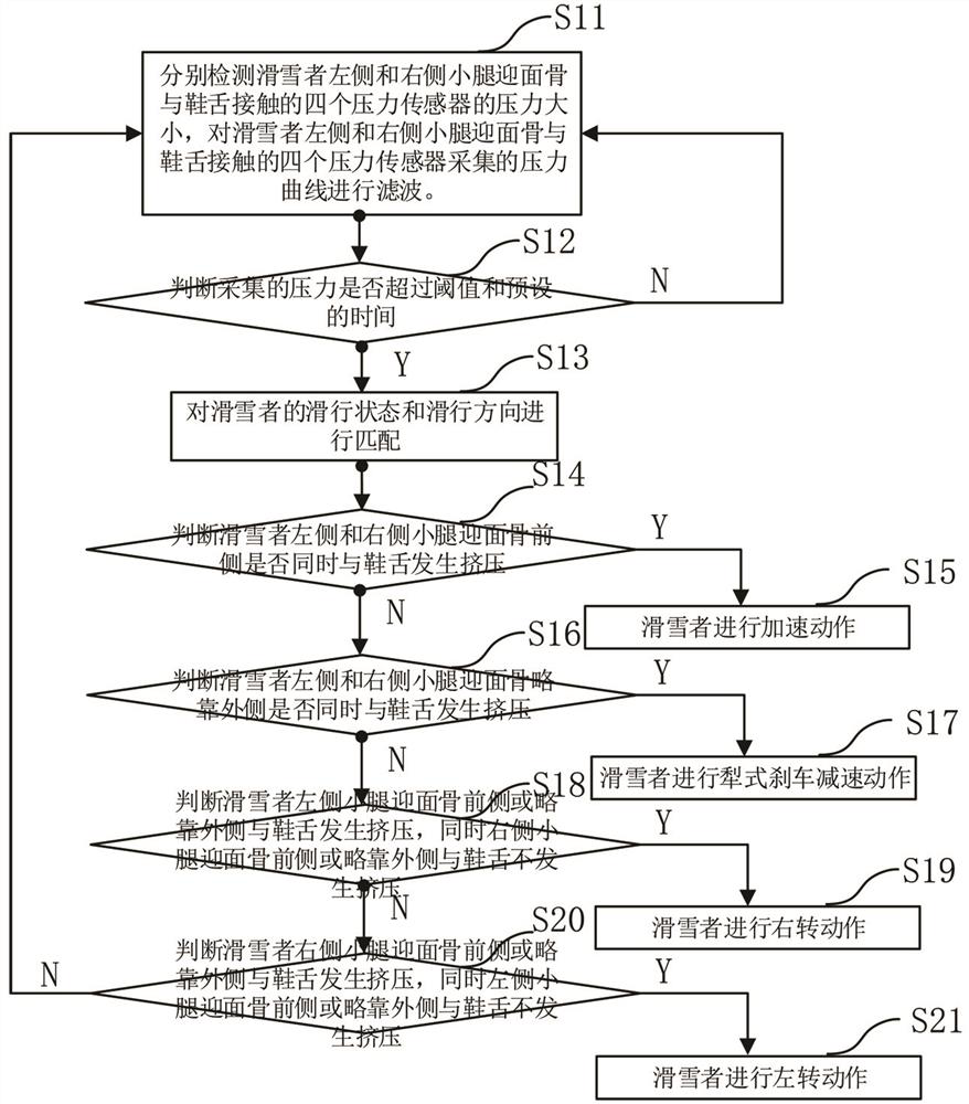
[0044] like image 3 : the program flowchart of the present invention.

[0045] Step S11: Detect the pressure of the four pressure sensors that are in contact with the tongue on the left and right calf of the skier respectively, and collect the pressure from the four pressure sensors that are in contact with the tongue on the left and right calf of the skier. The pressure curve is filtered.

[0046] Step S12: Judging whether the collected pressure exceeds the threshold and the preset time, if the collected pressure exceeds the threshold and the preset time, execute S13, otherwise return to S11.

[0047] Step S13: Match the skiing state and skiing direction of the skier.

[0048] Step S14: Determine whether the front sides of the skier's left and right calves are simultaneously pressed against the shoe tongue, and if the front sides of the skier's left and right calf are pressed against the tongue at the same time, go to S15; If the front sides of the skier's left and right ...

no. 2 example

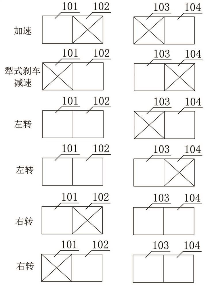
[0057] like figure 1 and figure 2 .

[0058] In the process of sliding, due to the small friction between the snowboard and the contacting snow track, there is a certain hysteresis between the transition of the skier’s sliding state and direction and the transition of the skier’s lower leg’s head-on bone force, so it can be calculated according to The direction of the skier's sliding track is estimated by the stress on the head-on bone of the skier's calf.

[0059] The first pressure sensor is placed on the position where the skier's left calf facing bone is squeezed slightly on the outside and the tongue of the shoe.

[0060] The second pressure sensor is placed at the position where the skier's left calf faces the front side of the bone and the shoe tongue is squeezed.

[0061] The third pressure sensor is placed at the position where the front side of the front bone of the skier's right calf and the shoe tongue are squeezed.

[0062] The fourth pressure sensor is placed ...


PUM


Abstract

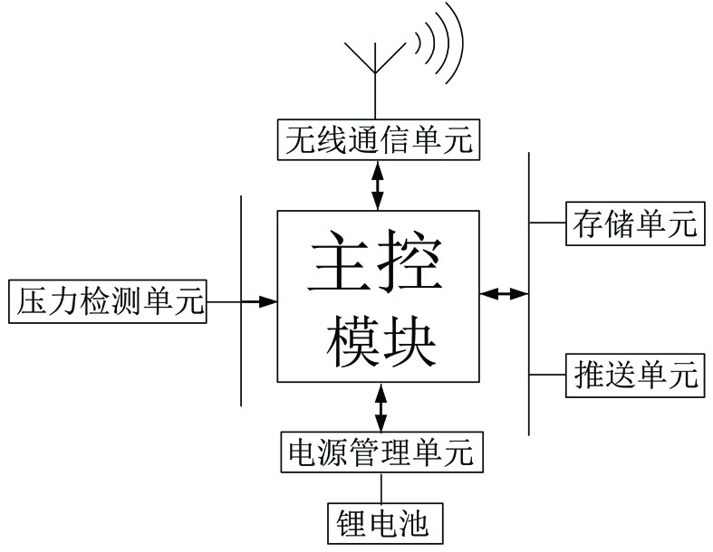
The sliding state and sliding direction detection device includes: a pressure detection unit, a storage unit, a wireless communication unit, a main control module, a power management unit and a lithium battery. Correlate the pressure of the four pressure sensors on the skier's left and right calf in contact with the shoe tongue with the skier's sliding state and direction, and detect the skier's left and right calf facing bone and tongue respectively The pressure of the four pressure sensors in contact with the pressure curve collected by the four pressure sensors in contact with the tongue of the left and right calf of the skier. When the applied pressure exceeds the threshold and the preset time, then efficient. According to the force of the four pressure sensors in contact with the tongue of the skier's left and right calf, the skier's skiing state and skiing direction are matched to determine the skier's skiing state and skiing direction. The invention simultaneously proposes a sliding state and a sliding direction detection and control method.

Description

technical field [0001] The invention relates to the technical field of ski resort safety guidance, in particular to a sliding state and sliding direction detection device and a control method thereof. Background technique [0002] During ski training, real-time acquisition of the skier's gliding status and exertion can provide effective and timely feedback to the skier and ski instructor. [0003] Most of the time, collisions between skiers cause far more damage than skiers fall, and any kind of injury is possible. In addition to mastering the correct wrestling posture, what is more important is how to avoid colliding with others. Real-time estimation of each skier's sliding track direction in the ski resort can effectively remind the skiers in the ski resort, avoid blind spot collisions, and avoid large and small turns interspersed with each other. [0004] Knowledge of skating posture and force: [0005] Standard posture for skiing: a support is formed by the bones of t...

Claims


Application Information

Patent Timeline
Patent Type & Authority Patents(China)
IPC IPC(8): A63B69/18
CPCA63B69/18A63B2220/56A63B2225/50
Inventor 宋彦震
Owner 郑旭纯
Learn More