Yarn selection control structure

A technology for controlling structure and yarn selection, which is applied in textiles and papermaking, weft knitting, knitting, etc. It can solve the problems of high production cost, difficulty in production and assembly, and economical reduction, so as to improve product economy and practicability, The effect of simplifying the internal structure and production process, reducing weight and production cost

Pending Publication Date: 2018-08-07
TANGSHAN WUGU ELECTROMECHANICAL EQUIP CO LTD
View PDF7 Cites 3 Cited by
  • Summary
  • Abstract
  • Description
  • Claims
  • Application Information

AI Technical Summary

Problems solved by technology

[0002] The yarn selection control structure of the existing thread changer is based on the principle of the gear box. Through the rack and pinion transmission, several groups of driving yarn selection components are driven to select the yarn. Through the yarn selection, whether a certain colored yarn participates in weaving is realized. , the selected yarn is processed by the yarn clamping and cutting device and other components of the yarn changer, so as to realize the thread changing function of the yarn changer. This type of yarn selection control structure is large in size, complex in structure, cumbersome in production process, and difficult to manufacture. And the disadvantages of difficult assembly, high production cost, and high failure rate in use make the economy greatly reduced

Method used


Image

  • Yarn selection control structure
  • Yarn selection control structure
  • Yarn selection control structure

Examples


Embodiment 1

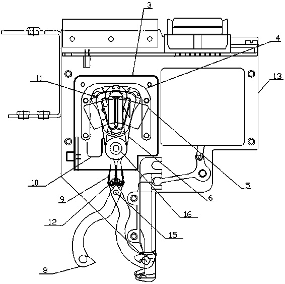
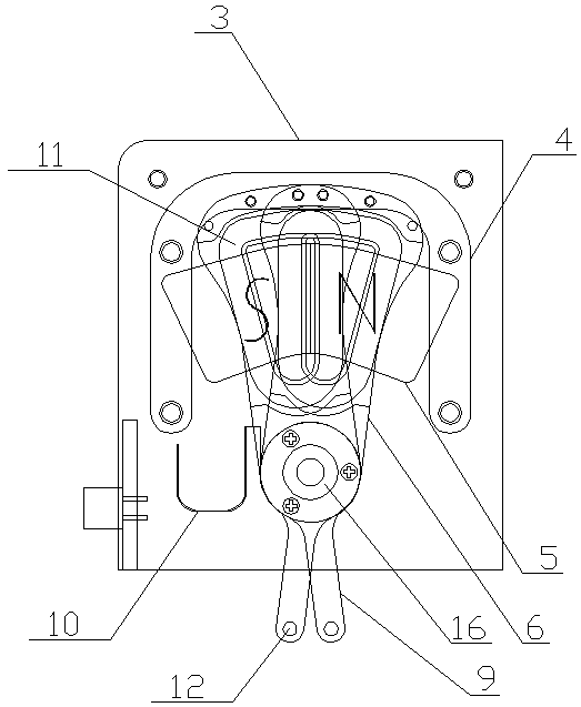
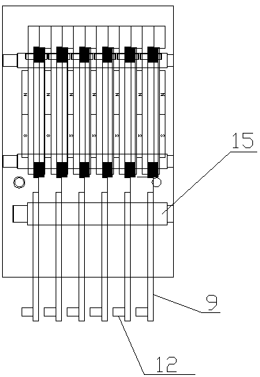
[0039] see figure 1 , figure 2 , image 3 , Figure 4 , Figure 5 , Image 6 , Figure 7 , Figure 8 , Figure 9 , Figure 10 , Figure 11 , Figure 12 , Figure 13 , Figure 14 , Figure 15 , a yarn selection control structure, including a controller housing 3 and a yarn feeding finger 8 arranged on the outer plate 13 of the yarn changer, a swing arm 6 is installed in the controller housing 3 through a rotating shaft 15, and the two sides of the swing arm 6 A permanent magnet 5 is arranged in parallel, and a coil 11 is arranged on the swing arm 6. The coil 11 and the permanent magnet 5 are placed in parallel to form a voice coil motor. The force of the wire, this thrust pushes the coil 11 to swing around its rotating shaft 15, that is, when the voice coil motor is energized and the direction of energization changes, the swing arm 6 can swing around the rotating shaft 15, and the swing arm 6 is driven by the voice coil motor. Yarn finger 8 swings to complete the...

Embodiment 2

[0049] see Figure 16 , Figure 17 , Figure 18 , the difference from Embodiment 1 is that: the yarn feeding finger 8 is installed on the controller housing 3 through the rotating shaft 15, and the swing arm 6 is provided with a wear-resistant block 2, which increases the stability and wear resistance of the swing arm 6, and the controller The housing 3 is provided with a partition plate 7 for isolating the yarn selection components and the yarns.

Embodiment 3

[0051] The difference from Embodiment 1 is that the swing arm 6 and the yarn feeding finger 8 are integrally formed.

[0052]The invention simplifies the internal structure and production process, adopts a new voice coil motor, is easy to manufacture and assemble, and improves product economy and practicability.


PUM


Abstract

The invention relates to a yarn changing device of a circular knitting machine, in particular to a yarn selection control structure. The yarn selection control structure comprises a controller shell and a yarn feeding finger arranged on a yarn changing device outer board, wherein a swinging arm is installed in the controller shell by virtue of a rotating shaft, two sides of the swinging arm are respectively provided with a permanent magnet in parallel, the swinging arm is provided with a coil, the coil is parallel to the permanent magnet to form a voice coilsound ring motor, and the swinging arm is driven by the voice coilsound ring motor to drive the yarn feeding finger to swing so as to complete the yarn selection action. By adopting the yarn selection control structure, the internal structure and the production flow are simplified; and by adopting a brand new voice coilsound ring motor, the yarn selection control structure is easy to produce and assemble, so that the economical performance and the practicability of the product can be improved.

Description

technical field [0001] The invention relates to a thread changer of a circular knitting machine, in particular to a yarn selection control structure. Background technique [0002] The yarn selection control structure of the existing thread changer is based on the principle of the gear box. Through the rack and pinion transmission, several groups of driving yarn selection components are driven to select the yarn. Through the yarn selection, whether a certain colored yarn participates in weaving is realized. , the selected yarn is processed by the yarn clamping and cutting device of the thread changer and other components, so as to realize the thread change function of the thread changer. This kind of yarn selection control structure is large in size, complex in structure, cumbersome in production process, and difficult to manufacture. And the disadvantages of difficult assembly, high production cost, and high failure rate in use make the economy greatly reduced. Contents of...

Claims


Application Information

Patent Timeline
Patent Type & Authority Applications(China)
IPC IPC(8): D04B15/58
CPCD04B15/58
Inventor 张燚
Owner TANGSHAN WUGU ELECTROMECHANICAL EQUIP CO LTD
Why Eureka
Try Eureka