A plastic circular loom

A technology of circular looms and plastics, applied in circular looms, looms, textiles, etc., can solve problems such as easy accumulation of dust, influence on warp wire transportation and weaving quality, and unfavorable airflow, etc., to achieve large contact area and small quantity , to avoid the effect of entanglement

Active Publication Date: 2020-04-17
雁峰集团有限公司
View PDF5 Cites 0 Cited by
  • Summary
  • Abstract
  • Description
  • Claims
  • Application Information

AI Technical Summary

Problems solved by technology

The door circle assembly is provided with a roller assembly, and there are multiple roller assemblies along the circumference of the door circle assembly. All the roller assemblies form a track for the shuttle to run. The general roller assembly includes a mandrel and multiple rollers, such as the invention patent In 201410209631.4, a high-speed plastic circular loom is disclosed. There are more than 2 track rollers between the upper door ring and the lower door ring to form a roller group for the shuttle to run. , which is not conducive to the air flow from the inside of the door ring assembly to the outside along the lower surface of the upper door ring and the upper surface of the lower door ring. The lower surface of the upper door ring and the upper surface of the lower door ring are easy to accumulate dust, which affects the warp conveying and weaving quality.

Method used


Image

  • A plastic circular loom
  • A plastic circular loom
  • A plastic circular loom

Examples


Embodiment 1

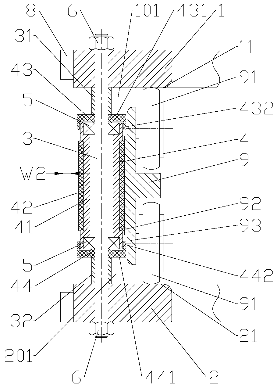
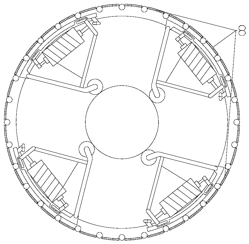
[0025] The invention provides a plastic circular loom, comprising a frame, a door ring assembly and a shuttle arranged on the frame. The door ring assembly includes an upper door ring 1 and a lower door ring 2, and a roller assembly is arranged between the upper door ring and the lower door ring , The roller assembly is arranged in multiple along the circumference of the door ring assembly, all the roller assemblies form a track for the shuttle 9 to run, such as figure 1 with figure 2 As shown, the roller assembly includes a mandrel 3 and a roller 4 sleeved on the mandrel 3. The lower surface 11 of the upper door ring 1, the upper surface 21 of the lower door ring 2, and two adjacent roller assemblies form a supply The thread passage through which the warp thread passes, the lower surface of the upper door ring and the upper surface of the lower door ring restrict the shuttle in the longitudinal direction. The outer circumference of the door ring assembly is provided with a warp...

Embodiment 2

[0038] reference figure 1 , In order to better guide the airflow to wash the lower surface of the upper door ring 1 and the upper surface of the lower door ring 2, the lower surface of the upper door ring and the upper surface of the lower door ring are both flat, the upper end of the drum 4 and the lower surface of the upper door ring An upper air outlet channel 101 is formed between the lower end of the drum 4 and the upper surface of the lower door ring 2. The shuttle runs at a high speed to squeeze the air flow outward and push the lower surface of the upper door ring and the upper surface of the lower door ring. The dust at the junction of the surface and the roller assembly is blown away. The lower surface of the upper door ring and the upper surface of the lower door ring are both flat, which can be understood as a plane parallel to the running plane of the shuttle 9. The planar structure is more conducive to the transport of warp yarns and reduces warp yarn wear. At the ...

Embodiment 3

[0045] Such as Figure 5 As shown, the cylinder 41 in this embodiment can be a simple hollow tube, and the bearing 5 is positioned by the retaining ring 45. The outer circumference of the cylinder 41 may not be provided with an annular groove, and the bottom surface of the shuttle 9 may not be provided with a boss. .

[0046] For other content not described in this embodiment, reference may be made to Embodiment 1 and Embodiment 2.


PUM


Abstract

The invention discloses a plastic circular loom, and belongs to the field of plastic weaving machinery, which solves the problem that dust is easy to accumulate on the lower surface of an upper door ring and the upper surface of a lower door ring in the prior art. The technical scheme for solving the problem is mainly that a roller assembly comprises a mandrel and a roller sleeving the mandrel, athread passing channel for a warp to pass through is formed between the lower surface of the upper door ring, the upper surface of the lower door ring and two adjacent roller assemblies, a warp separator is arranged on the periphery of the door ring assembly, a through groove is formed in the warp separator, the warp passes through the through groove one to one, the total flow area of the throughgroove corresponding to each thread passing channel is less than the flow area of the thread passing channel, and a shuttle operates at high speed to squeeze a gas in the thread passing channel to form a gas flow to blow out the dust on the lower surface of the upper door ring and the upper surface of the lower door ring. The plastic circular loom disclosed by the invention is mainly used for blowing out the dust on the lower surface of the upper door ring and the upper surface of the lower door ring during the high speed operation of the shuttle.

Description

Technical field [0001] The invention relates to a plastic weaving machine, in particular to a plastic circular loom. Background technique [0002] In the current plastic circular loom, the warp thread passes through the door ring assembly, and the shuttle runs along the inner ring of the door ring assembly in a circular motion at high speed to realize the cross weaving of the warp yarn and the weft yarn. The door ring assembly is provided with roller assemblies, and there are multiple roller assemblies arranged along the circumference of the door ring assembly. All roller assemblies form a track for the shuttle to run. A general roller assembly includes a mandrel and multiple rollers, such as invention patents. A high-speed plastic circular loom is disclosed in 201410209631.4. There are two or more track rollers between the upper door ring and the lower door ring to form a roller set for the shuttle to run. Because there are more track rollers and inclined steps , It is not cond...

Claims


Application Information

Patent Timeline
Patent Type & Authority Patents(China)
IPC IPC(8): D03D37/00D03J1/00
CPCD03D37/00D03J1/002
Inventor 陈志淡陈向荣邹虎生许德新梁海立陈洁清吴阳春段李平
Owner 雁峰集团有限公司
Why Eureka
Try Eureka