Sewing machine and cloth conveying mechanism thereof

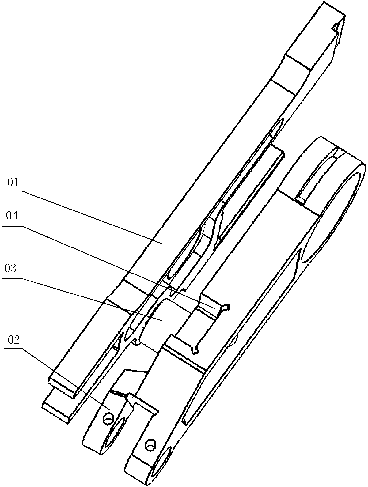
A cloth feeding mechanism and sewing machine technology, applied in the direction of cloth feeding mechanism, sewing machine components, sewing equipment, etc., can solve the problems of poor working reliability of the cloth feeding mechanism, affecting the stable operation of the cloth feeding mechanism, and jamming of the slider 03, etc. The effect of improving operation and work reliability and overcoming the problem of sticking

Active Publication Date: 2018-08-10
JACK SEWING MASCH CO LTD
View PDF6 Cites 2 Cited by
  • Summary
  • Abstract
  • Description
  • Claims
  • Application Information

AI Technical Summary

Problems solved by technology

Obviously, the power transmission of the existing cloth feeding mechanism is realized by the slider 03 and the chute 04. In actual work, when the slider 03 moves relative to the chute 04, there is a violent Friction may cause the slider 03 to be stuck, which seriously affects the stable operation of the cloth feeding mechanism. Therefore, the working reliability of the cloth feeding mechanism of the existing sewing machine is relatively poor

Method used


Image

  • Sewing machine and cloth conveying mechanism thereof
  • Sewing machine and cloth conveying mechanism thereof
  • Sewing machine and cloth conveying mechanism thereof

Examples


Embodiment Construction

[0043] The following will clearly and completely describe the technical solutions in the embodiments of the present invention with reference to the accompanying drawings in the embodiments of the present invention. Obviously, the described embodiments are only some, not all, embodiments of the present invention. Based on the embodiments of the present invention, all other embodiments obtained by persons of ordinary skill in the art without making creative efforts belong to the protection scope of the present invention.

[0044] In order to enable those skilled in the art to better understand the solution of the present invention, the present invention will be further described in detail below in conjunction with the accompanying drawings and specific embodiments.

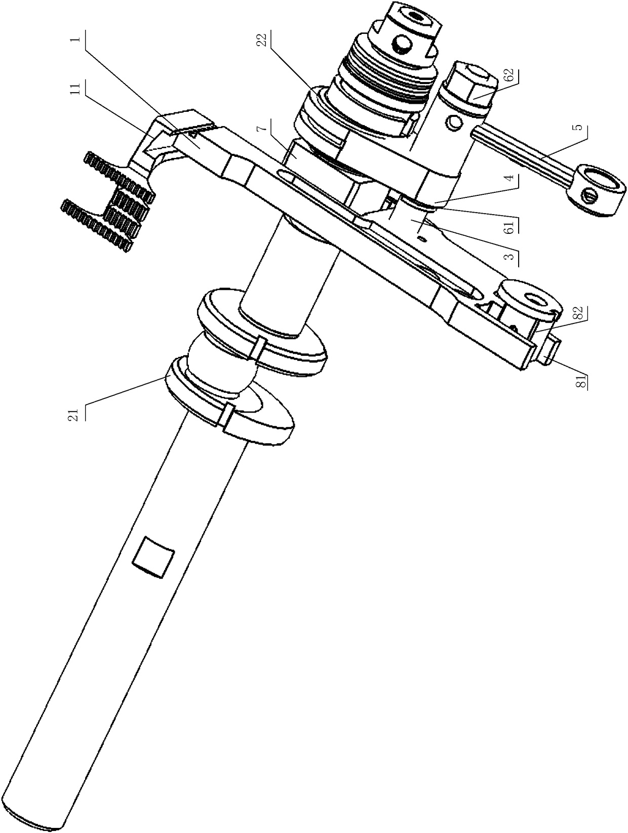
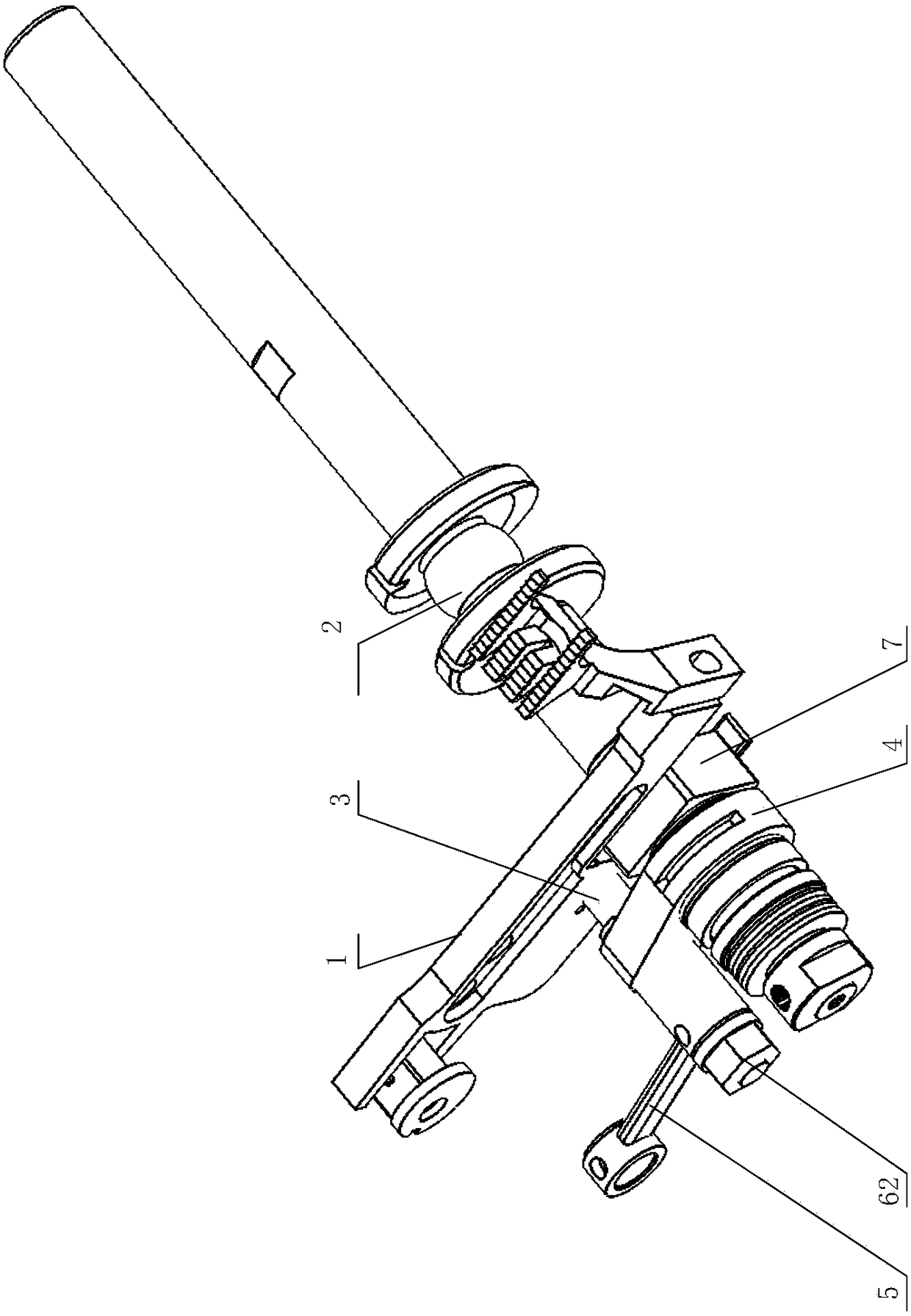
[0045] Please refer to figure 2 and image 3 , figure 2 Schematic diagram of the structure of the cloth feeding mechanism provided by an embodiment of the present application; image 3 for figure 2 another vi...


PUM


Abstract

The invention discloses a cloth conveying mechanism of a sewing machine. The mechanism comprises a feed dog rack, a crankshaft assembly, a cloth conveying connection rod fixedly arranged on the side of the feed dog rack and used for being connected with a differential motion adjustment mechanism and a cloth conveying swing rod, wherein the two ends of the cloth conveying swing rod penetrate through the cloth conveying connection rod and the crankshaft assembly respectively. By means of the cloth conveying mechanism, one end of the cloth conveying connection rod is fixedly arranged on the sidesurface of the feed dog rack, the cloth conveying swing rod penetrates through the other end of the cloth conveying connection rod, and accordingly the feed dog rack is connected with the cloth conveying swing rod to replace an original sliding groove and sliding block structure; the problem is solved that clamping stagnation is caused when a sliding block moves relative to a sliding groove, convenience is provided for the feed dog rack to move more stably, and therefore the cloth conveying mechanism is high in working reliability. The invention further discloses the sewing machine with high working efficiency.

Description

technical field [0001] The invention relates to the technical field of textile equipment, in particular to a cloth feeding mechanism of a sewing machine. The invention also relates to a sewing machine. Background technique [0002] The working principle of the existing sewing machine is that the needle bar drives the lead wire to pass through the looper with the winding thread on the bottom of the textile under the drive of the driving device to interweave the lead thread and the winding thread to realize sewing. In view of the special working principle of the existing sewing machine, it has the advantages of fast sewing speed, good sewing quality, and convenient operation. It is deeply favored by people and is widely used in clothing, household and other fields. [0003] Existing sewing machines usually include a needle bar stabbing and jumper mechanism, a differential adjustment mechanism, a cloth feeding mechanism, a looper thread hooking mechanism, and the like. Wherei...

Claims


Application Information

Patent Timeline
Patent Type & Authority Applications(China)
IPC IPC(8): D05B27/02
CPCD05B27/02
Inventor 李卫超杨聪聪王志
Owner JACK SEWING MASCH CO LTD
Why Eureka
Try Eureka