Al technical title is built by PatSnap Al team. It summarizes the technical point description of the patent document.
A technology for auxiliary equipment and cable marking, applied in the field of electric power, can solve the problems of difficult digging of broken soil, cumbersome and complicated process, inconvenience of manual digging, etc., and achieve the effects of convenient digging, simple operation and high labor intensity.
Inactive Publication Date: 2018-08-10
郭考香
View PDF0 Cites 6 Cited by
Summary
Abstract
Description
Claims
Application Information
AI Technical Summary
This helps you quickly interpret patents by identifying the three key elements:
Problems solved by technology
Method used
Benefits of technology
Problems solved by technology
[0003] In order to solve the above problems, the present invention provides a kind of intelligent auxiliary equipment for cable marker piles, which can solve the problem of digging pits by personnel in the process of installing cable marker piles. When digging a pit, the personnel need to use tools to dig the pit, and it takes a long time for the personnel to dig the pit to meet the requirements of the work. It is easy to cause safety hazards when bending over for a long time to dig the soil. When digging the pit, it is necessary to manually shovel away the broken soil. The broken soil on the side is not easy to dig out, manual digging is inconvenient, the process takes a long time, the labor intensity is high and the efficiency is low. It can realize the function of automatic digging and shoveling of the soil, automatic digging, automatic multi-directional cutting Flat, fast completion of work requirements, automatic excavation of crushed soil, automatic centralized stacking of crushed soil, convenient digging, no need for personnel operation, ensuring personnel safety, short time-consuming, and has the advantages of simple operation, low labor intensity and high work efficiency.
Method used
Image
Click on the blue label to locate the original text in one second.
Reading with bidirectional positioning of images and text.
Examples
Embodiment Construction
[0029] In order to make it easy to understand the technical means, creation features, achieved goals and effects of the present invention, the present invention will be further described below with reference to the specific figures. It should be noted that the embodiments in the present application and the features of the embodiments may be combined with each other in the case of no conflict.
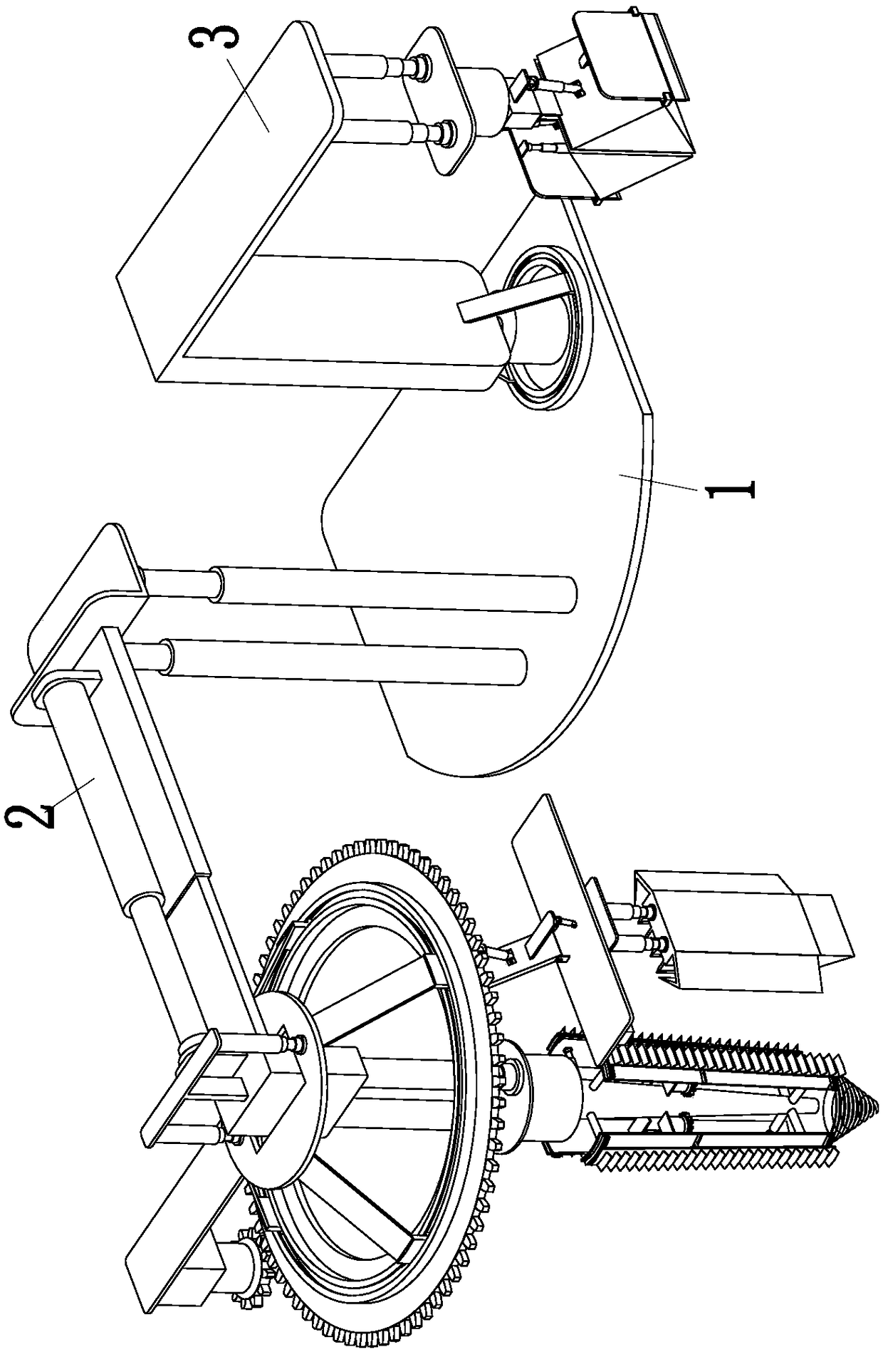
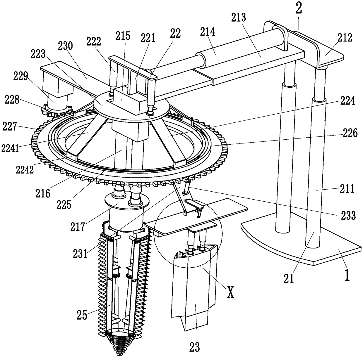
[0030] like Figure 1 to Figure 8 As shown, in order to achieve the above object, the present invention adopts the following technical solutions: a kind of intelligent auxiliary equipment for cable marking piles, comprising a mobile platform 1, a digging device 2 and a shoveling device 3, and the digging device 2 digs and cuts the soil pit. The digging device 3 digs away the broken soil in the soil pit. The front end of the mobile platform 1 is installed with the digging device 2 , and the rear right side of the mobile platform 1 is installed with the shoveling device 3 .
[0031] The ...
PUM
Abstract
The invention relates to a cable marker pile intelligent auxiliary device. The cable marker pile intelligent auxiliary device comprises a moving platform, a pit digging device and a shoveling off device; the pit digging device is arranged at the front end of the moving platform, the shoveling off device is arranged on the right side of the rear end of the moving platform, and through the device, the problems that in the existing cable marker pile mounting process, manual pit digging is needed, after pit digging, pulverizing soil needs to the shoveled off manually, the process is tedious and complex, during pit digging, a person needs to dig the pit through a tool, after long-time pit digging, the requirement needed by work is met, long-time bowing for earth cutting easily causes potentialsafety hazards, during pit digging, the pulverizing soil needs to be manually shoveled off, the pulverizing soil on the side of the soil pit is not prone to shoveling off, manual shoveling is not convenient, the process needs to consume long time, labor intensity is large, and the efficiency is low are solved. Through the device, automatic earth cutting and automatic shoveling off can be achieved.
Description
technical field [0001] The invention relates to the field of electric power, in particular to an intelligent auxiliary equipment for cable marker posts. Background technique [0002] Cable marker stakes are also known as power cable marker stakes, marker stakes, natural gas marker stakes channel vertical marker stakes, commonly used in electric power, communication, gas, tap water, railway geographical pipeline path channel indication signs and warning signs, used in downtown, scenic spots , green belts, bushes, pipeline path indication on both sides of pipe jacking, high strength, the product is made of new unsaturated resin material, pressed at high temperature, impact resistance, wear resistance, high temperature resistance, corrosion resistance, so the service life is long 30 years, the appearance is beautiful, the product can be made into various colors, the font pattern is clear, the warning is obvious and can beautify the urban environment, prevent theft, the syntheti...
Claims
Application Information
Patent Timeline
Application Date:The date an application was filed.
Publication Date:The date a patent or application was officially published.
First Publication Date:The earliest publication date of a patent with the same application number.
Issue Date:Publication date of the patent grant document.
PCT Entry Date:The Entry date of PCT National Phase.
Estimated Expiry Date:The statutory expiry date of a patent right according to the Patent Law, and it is the longest term of protection that the patent right can achieve without the termination of the patent right due to other reasons(Term extension factor has been taken into account ).
Invalid Date:Actual expiry date is based on effective date or publication date of legal transaction data of invalid patent.