Water supply and drainage structure for building automatic control equipment

A building automation, water supply and drainage technology, applied in the direction of water saving, water supply main pipeline, water supply pipeline system, etc., can solve problems such as current limitation, and achieve the effect of preventing device damage, protecting water safety, and water quality.

Inactive Publication Date: 2018-08-10
WUXI DACHENG TIANXIA INTELLIGENT TECH CO LTD XISHAN BRANCH
View PDF0 Cites 3 Cited by
  • Summary
  • Abstract
  • Description
  • Claims
  • Application Information

AI Technical Summary

Problems solved by technology

In the water supply and drainage system, there is currently no device that restricts the flow of water flowing through the pipeline

Method used


Image

  • Water supply and drainage structure for building automatic control equipment
  • Water supply and drainage structure for building automatic control equipment

Examples


Embodiment Construction

[0014] In order to make the technical means, creative features, objectives and effects of the present invention easy to understand, the present invention will be further explained below in conjunction with specific embodiments.

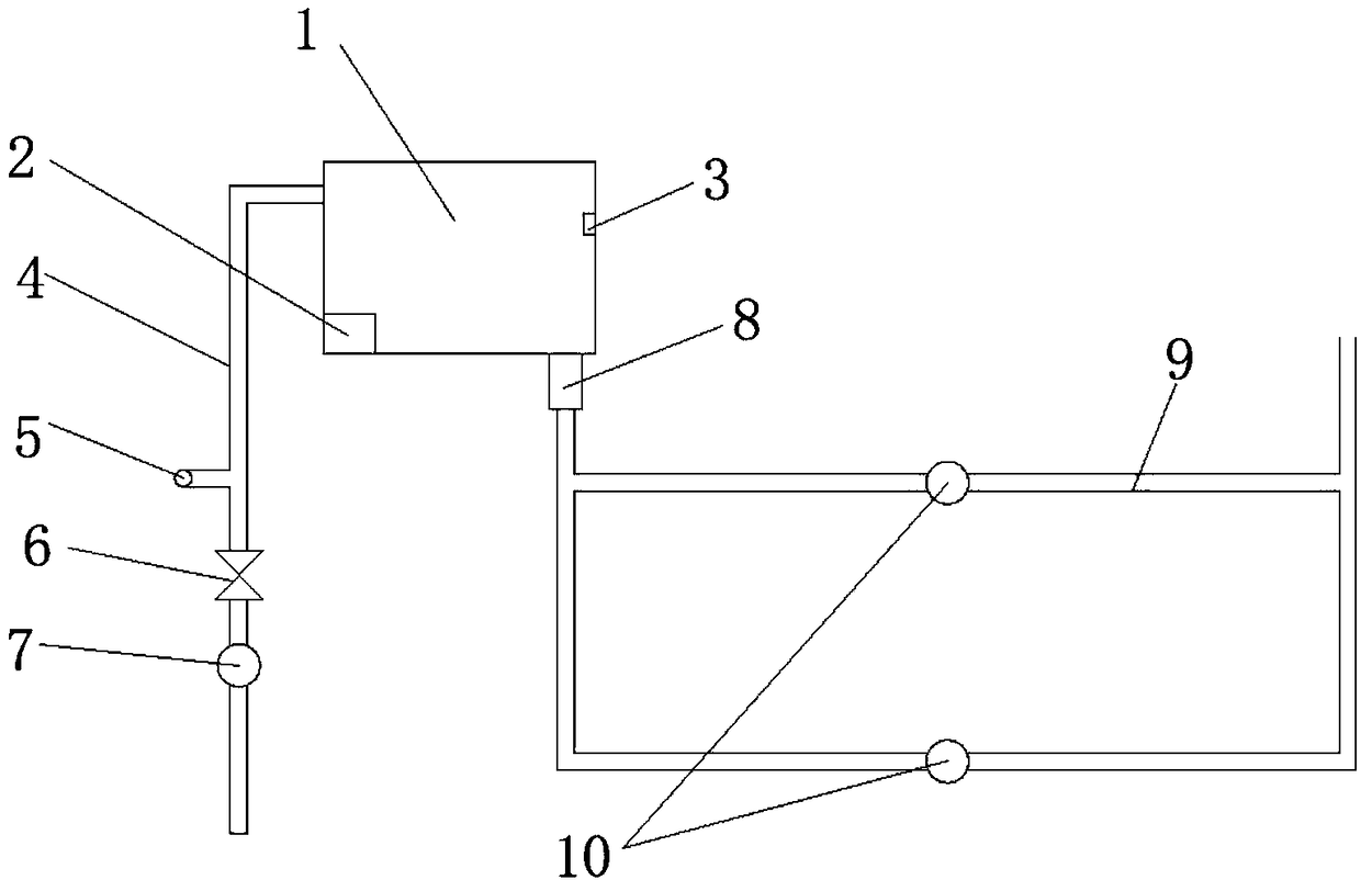
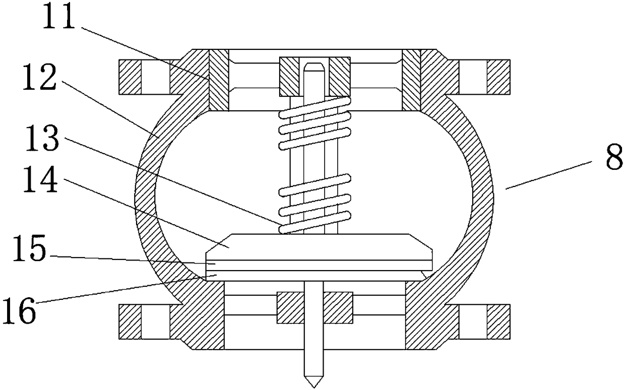
[0015] Such as Figure 1-2 As shown, a water supply and drainage structure for building automatic control equipment includes a water tank 1, a filter 2 is provided at the lower end of the water tank 1, a water level sensor 3 is provided on the inner side wall of the water tank 1, and one side of the water tank 1 is provided Water inlet pipe 4, one side of the water inlet pipe 4 is provided with a drain pipe 5, the water inlet pipe 4 is provided with a check valve 6 and a No. 1 water pump 7, and the No. 1 water pump 7 is located below the check valve 6, the water tank 1. A flow limiting valve 8 is provided at the lower end of the flow limiting valve 8, a water collecting pipe 9 is provided at the lower end of the flow restricting valve 8, and a second wat...


PUM


Abstract

The invention discloses a water supply and drainage structure for building automatic control equipment. The water supply and drainage structure comprises a water tank, wherein a filter is arranged atthe lower end of the interior of the water tank; a water level sensor is arranged on the inner sidewall of the water tank; a water intake pipe is arranged at one side of the water tank; a drainage pipe is arranged at one side of the water intake pipe; a check valve and a No.1 water pump are arranged in the water intake pipe, and the No.1 water pump is arranged under the check valve; a flow-limiting valve is arranged at the lower end of the water tank; a water collection pipeline is arranged at the lower end of the flow-limiting valve; a No.2 water pump is arranged in the water collection pipeline. The water supply and drainage structure provided by the invention is simple in structure, reasonable in design, convenient in operation and management and reliable in water supply, and water supply and drainage demands of the building automatic control equipment can be satisfied.

Description

Technical field [0001] The invention relates to a building equipment automatic control system, in particular to a water supply and drainage structure for building automatic control equipment. Background technique [0002] Building equipment automatic control system: an integrated collective name for cold and heat source systems, air conditioning and ventilation systems, fan disk systems, lighting systems, elevator systems, and water supply and drainage systems. The system mainly uses operating status monitoring and fault monitoring to efficiently manage and control various equipment in the building. While providing the best comfortable environment and modern management mode, it greatly reduces energy consumption. Therefore, it is widely used in offices and hotels. , Hospitals, shopping malls and other buildings. In the water supply and drainage system, there is currently no device for restricting the flow of water flowing through the pipeline. To this end, we propose a water su...

Claims


Application Information

Patent Timeline
Patent Type & Authority Applications(China)
IPC IPC(8): E03B7/04E03B11/02E03B11/16
CPCE03B7/04E03B7/07E03B7/071E03B11/02Y02A20/00
Inventor 韩瀚
Owner WUXI DACHENG TIANXIA INTELLIGENT TECH CO LTD XISHAN BRANCH
Why Eureka
Try Eureka