
Low-wear rotary compensator

A rotary compensator, low-wear technology, used in pipeline expansion compensation devices, adjustable connections, pipes/pipe joints/pipe fittings, etc. question

Inactive Publication Date: 2018-08-10
高玉琴
View PDF5 Cites 2 Cited by
  • Summary
  • Abstract
  • Description
  • Claims
  • Application Information

AI Technical Summary

Problems solved by technology

[0002] The structure of the rotary compensator generally includes an outer cylinder and an inner cylinder. One end of the inner cylinder extends into the outer cylinder. There is a sealing packing between the outer cylinder and the inner cylinder. The two sides of the sealing packing are clamped to cause radial expansion of the sealing packing. The position of the packing relative to the outer cylinder is fixed, and the inner cylinder and the outer cylinder can rotate relative to each other. When the inner cylinder rotates, there will be friction between the sealing packing, which will wear the sealing packing and cause the sealing performance to decline; in addition, clamping the sealing packing requires applying Sufficient pre-tightening force makes the friction between the sealing packing and the outer cylinder and inner cylinder at the maximum state, and the sealing packing is easy to wear; in addition, the rotation between the outer cylinder and the inner cylinder is not flexible, so that the compensation for the pipeline is not timely

Method used


Image

  • Low-wear rotary compensator

Examples


Embodiment Construction

[0008] The specific embodiment of the present invention will now be described in conjunction with the accompanying drawings.

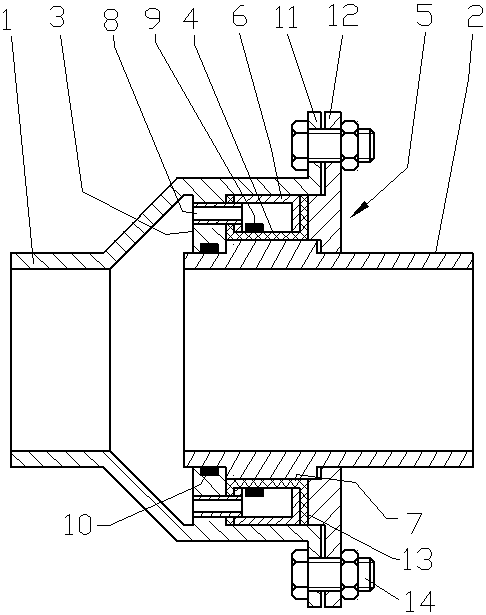
[0009] A low-wear rotary compensator, which includes an outer cylinder 1 and an inner cylinder 2. The outer cylinder has a variable diameter structure. The left section of the inner cylinder is located in the large diameter section of the outer cylinder. It is characterized in that the outer wall of the inner cylinder is covered with a rubber sleeve 4 , the outer wall of the rubber sleeve is covered with a pressure-bearing cylinder 5, and the left and right ends of the pressure-bearing cylinder extend radially inward respectively with a left annulus and a right annulus, and the inner circles of the left annulus and the right annulus are connected with the inner circle of the rubber sleeve. The outer wall is in contact, and the left and right ends of the rubber sleeve extend radially outward respectively to a left flange and a right flange, and the left ...


PUM


Abstract

The invention relates to a low-wear rotary compensator. The low-wear rotary compensator comprises an outer cylinder (1) and an inner cylinder (2), wherein the outer wall of the inner cylinder is sleeved with a rubber sleeve (4), and the rubber sleeve is sleeved with a pressure-bearing cylinder (5). Annular surfaces extending inward are correspondingly arranged at the two ends of the pressure-bearing cylinder, and flanges extending outward are correspondingly arranged on the two ends of the rubber sleeve. A baffle ring (3) is arranged on the left side of the rubber sleeve, and a gland (5) is arranged on the right side of the rubber sleeve. A left annular surface of the pressure-bearing cylinder is hermetically connected with a plurality of drainage tubes (8), and the drainage tubes sequentially penetrate through the left flange and the baffle ring of the rubber sleeve. The low-wear rotary compensator is characterized in that the left annular surface of the rubber sleeve is in close contact with the baffle ring and the rubber sleeve and the pressure-bearing cylinder form a closed cavity after compressed by the gland, the pressure of fluid causes the rubber sleeve to cling to the outer wall of the inner cylinder to realize the seal between the inner cylinder and the outer cylinder. The greater the pressure of the fluid of the rubber sleeve, the closer the contact between the rubber sleeve and the inner cylinder. When the inner cylinder rotates relative to the outer cylinder, the friction force borne by the rubber sleeve is small, and the wearing capacity of the rubber sleeve can be automatically compensated under the action of the inner pressure, and the sealing performance is maintained.

Description

technical field [0001] The invention relates to a rotary compensator, which is used for compensating thermal expansion and contraction of hot water pipes. Background technique [0002] The structure of the rotary compensator generally includes an outer cylinder and an inner cylinder. One end of the inner cylinder extends into the outer cylinder. There is a sealing packing between the outer cylinder and the inner cylinder. The two sides of the sealing packing are clamped to cause radial expansion of the sealing packing. The position of the packing relative to the outer cylinder is fixed, and the inner cylinder and the outer cylinder can rotate relative to each other. When the inner cylinder rotates, there will be friction between the sealing packing, which will wear the sealing packing and cause the sealing performance to decline; in addition, clamping the sealing packing requires applying Sufficient pre-tightening force makes the friction between the sealing packing and the ...

Claims


Application Information

Patent Timeline
IPC IPC(8): F16L27/087F16L51/00
CPCF16L27/087F16L51/00
Inventor 高玉琴
Owner 高玉琴
Learn More